
Owner's Manual
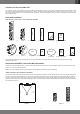
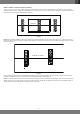
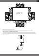
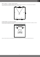
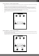
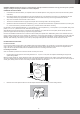
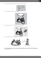
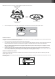
Table Of Contents
- THANK YOU FOR CHOOSING JBL®
- PACKAGE CONTENTS
- SPEAKER PLACEMENT FOR IN-CEILING AND IN-WALL
- IN-WALL SPEAKER - LEFT AND RIGHT PLACEMENT
- IN-WALL SPEAKER - CENTER CHANNEL PLACEMENT
- IN-WALL SPEAKER - SURROUND PLACEMENT
- IN-WALL SPEAKEAR - 5.1-CHANNEL SYSTEMS PLACEMENT
- IN-WALL SPEAKEAR - 7.1-CHANNEL SYSTEMS PLACEMENT
- IN-CEILING SPEAKER - LEFT AND RIGHT PLACEMENT
- IN-CEILING SPEAKEAR - 5.1-CHANNEL SYSTEMS PLACEMENT
- IN-CEILING SPEAKEAR - 7.1-CHANNEL SYSTEMS PLACEMENT
- IN-CEILING INSTALLATION GUIDE
- PAINTING THE GRILLE
- BOUNDARY COMPENSATION CONTROL
- SPECIFICATIONS
- MERCI D'AVOIR CHOISI JBL®
- CONTENU DE L’EMBALLAGE
- POSITIONNEMENT DES ENCEINTES DANS UN PLAFOND ET DANS UN MUR
- ENCEINTE ENCASTRÉE - POSITIONNEMENTS GAUCHE ET DROIT
- ENCEINTE ENCASTRÉE - POSITIONNEMENT DU CANAL CENTRAL
- ENCEINTE ENCASTRÉE - POSITIONNEMENT DU SURROUND
- ENCEINTE ENCASTRÉE - POSITIONNEMENT DU SYSTÈME POUR 5.1 CANAUX
- ENCEINTE ENCASTRÉE - POSITIONNEMENT DU SYSTÈME POUR 7.1 CANAUX
- ENCEINTE EN PLAFOND - POSITIONNEMENTS GAUCHE ET DROIT
- ENCEINTE EN PLAFOND - POSITIONNEMENT DU SYSTÈME POUR 5.1 CANAUX
- ENCEINTE EN PLAFOND - POSITIONNEMENT DU SYSTÈME POUR 7.1 CANAUX
- GUIDE D’INSTALLATION EN PLAFOND
- PEINTURE DE LA GRILLE
- COMMANDE DE COMPENSATION DE BORD
- CARACTÉRISTIQUES TECHNIQUES
- VIELEN DANK FÜR DEN KAUF EINES JBL®-PRODUKTS!
- LIEFERUMFANG
- LAUTSPRECHERPOSITIONIERUNG FÜR DECKEN- UND WANDEINBAU
- WANDEINBAU-LAUTSPRECHER -–LINKE UND RECHTE POSITIONIERUNG
- WANDEINBAU-LAUTSPRECHER – POSITIONIERUNG DES CENTER-KANALS
- WANDEINBAU-LAUTSPRECHER – SURROUND-POSITIONIERUNG
- UNTERPUTZ-LAUTSPRECHER – POSITIONIERUNG VON 5.1-KANAL-SYSTEMEN
- UNTERPUTZ-LAUTSPRECHER – POSITIONIERUNG VON 7.1-KANAL-SYSTEMEN
- DECKENEINBAULAUTSPRECHER – POSITIONIERUNG LINKS UND RECHTS
- DECKENEINBAU-LAUTSPRECHER – POSITIONIERUNG VON 5.1-KANAL-SYSTEMEN
- DECKENEINBAU-LAUTSPRECHER – POSITIONIERUNG VON 7.1-KANAL-SYSTEMEN
- DECKENEINBAUANLEITUNG
- ANSTRICH DES GITTERS
- BOUNDARY-COMPENSATION-STEUERUNG
- TECHNISCHE DATEN
- MUITO OBRIGADO POR ESCOLHER A JBL®
- CONTEÚDO DA EMBALAGEM
- POSICIONAMENTO DA CAIXA DE SOM NO TETO E NA PAREDE
- CAIXA DE SOM DE PAREDE - POSICIONAMENTO COM DUAS CAIXAS (ESQUERDA E DIRETA)
- CAIXAS DE SOM DE PAREDE - POSICIONAMENTO DO CANAL CENTRAL
- CAIXAS DE SOM DE PAREDE - POSICIONAMENTO SURROUND
- CAIXA DE SOM DE PAREDE - POSICIONAMENTO DE SISTEMA DE 5.1 CANAIS
- CAIXA DE SOM DE PAREDE - POSICIONAMENTO DE SISTEMA DE 7.1 CANAIS
- CAIXA DE SOM DE TETO - POSICIONAMENTO COM DUAS CAIXAS (ESQUERDA E DIRETA)
- CAIXA DE SOM DE TETO - POSICIONAMENTO DE SISTEMA DE 5.1 CANAIS
- CAIXA DE SOM DE TETO - POSICIONAMENTO DE SISTEMA DE 7.1 CANAIS
- INSTRUÇÕES PARA INSTALAÇÃO NO TETO
- PINTURA DA GRADE
- CHAVE DE COMPENSAÇÃO DE PROXIMIDADE
- INFORMAÇÕES TÉCNICAS
- БЛАГОДАРИМ ВАС ЗА ВЫБОР ПРОДУКЦИИ JBL®
- КОМПЛЕКТАЦИЯ
- УСТАНОВКА АКУСТИЧЕСКИХ СИСТЕМ В ПОТОЛКЕ И В СТЕНЕ
- НАСТЕННАЯ АКУСТИЧЕСКАЯ СИСТЕМА: РАЗМЕЩЕНИЕ ЛЕВОЙ И ПРАВОЙ КОЛОНКИ
- РАЗМЕЩЕНИЕ АКУСТИЧЕСКИЙ СИСТЕМЫ ЦЕНТРАЛЬНОГО КАНАЛА
- АКУСТИЧЕСКАЯ СИСТЕМА ДЛЯ МОНТАЖА В СТЕНУ: РАЗМЕЩЕНИЕ КОЛОНОК ОБЪЕМНОГО ЗВУЧАНИЯ
- РАЗМЕЩЕНИЕ 5.1-КАНАЛЬНЫХ СИСТЕМ
- РАЗМЕЩЕНИЕ 7.1-КАНАЛЬНЫХ СИСТЕМ
- АКУСТИЧЕСКАЯ СИСТЕМА ДЛЯ МОНТАЖА В ПОТОЛОК: РАЗМЕЩЕНИЕ АКУСТИЧЕСКИХ СИСТЕМ ЛЕВОГО И ПРАВОГО КАНАЛОВ
- ПОТОЛОЧНАЯ АКУСТИЧЕСКАЯ СИСТЕМА: РАЗМЕЩЕНИЕ 5.1-КАНАЛЬНЫХ СИСТЕМ
- ПОТОЛОЧНАЯ АКУСТИЧЕСКАЯ СИСТЕМА: РАЗМЕЩЕНИЕ 7.1-КАНАЛЬНЫХ СИСТЕМ
- РУКОВОДСТВО ПО МОНТАЖУ В ПОТОЛКЕ
- ПОКРАСКА ЗАЩИТНОЙ РЕШЕТКИ
- НАСТРОЙКА ГРАНИЧНОЙ КОМПЕНСАЦИИ
- Технические характеристики
- 感谢您选择 JBL®
- 包装内容
- 扬声器吸顶式及入墙式摆放
- 规格
- JBL®을 선택해 주셔서 감사합니다
- 패키지 구성품
- 천장 설치형 및 벽 설치형 스피커 배치
- 사양

English
8
WARNING: HARMAN International assumes no responsibility for improper installation of hardware or for any personal injuries or product
damages resulting from improper installation or a fallen loudspeaker.
PREPARING THE HOOK-UP WIRE
1. First determine the distance between your amplier and the most distant speaker in each group (fronts, surrounds, back surrounds, passive
subwoofers).
2. Now make the hookup wires for all speakers in each group this length, even if one speaker is much closer to your amplier than the other.
This will help maintain proper signal balance. Remember to make extra wires for bi-amp or bi-wire usage should this be selected.
3. Strip off 3/8" of insulation from both ends of each conductor.
4. Twist each set of stranded wires into a tightly bunched spiral. Run wires through walls to the mounting positions.
5. Speakers and electronics terminals have corresponding (+) and (–) terminals. Most manufacturers of speakers and electronics, including JBL,
Inc., use red to denote the (+) terminal and black for the (–) terminal. Please conrm before connecting.
It is important to connect all speakers identically: (+) on the speaker to (+) on the amplier and (–) on the speaker to (–on the amplier. Wiring "out of
phase" (+ to - and - to +) results in thin sound, weak bass and poor imaging.
With multichannel surround sound systems, connecting all of the speakers in your system with the correct polarity remains equally important to
preserve the proper ambience and frequency response of the program material.
Now nd a visual difference between the two conductors of each molded pair of speaker wires. Differentiating marks can be a different color wire
(copper or silver); a strand of yarn in one conductor; thin, raised ribs on one part of the outer insulation; or a printed marking on one part of the outer
insulation. It doesn’t matter which of the two strands go to the (+) and (–) on the speakers and ampliers, as long as all speakers are connected
identically. When attaching to the back box, push on the top of the spring-loaded post and insert the bare wire into the hole on the side.
IN-CEILING INSTALLATION GUIDE
For New Construction
If you wish to pre-install a rough-in frame for the speakers before the drywall is installed in new construction, you will need to purchase the correct
rough-in frame kit for your loudspeaker model from your authorized JBL Synthesis dealer. Detailed mounting instructions are supplied with the
rough-in kit. After the drywall is installed, follow the installation instructions in For Existing Construction, below.
For Existing Construction
Note: The installation procedure is the same for all models covered by this manual.
1. Ensure that the drywall, plywood or other ceiling material is 1/2" - 2" (13mm - 51mm) thick and capable of withstanding the weight of the
speaker being installed.
Make sure to allow at least 3/4" (19mm) between the edge of the supplied installation template and any rafters or other obstructions behind the
wall, so the speaker's locking mechanism will have room to engage fully Perform an obstruction survey to be sure that there are no studs, lengths of
conduit, pipes, heating ducts or air returns in the ceiling cavity that will interfere with the speaker.
Mounting
Opening
3/4"
(19mm)
3/4"
(19mm)
3/4"
(19mm)
2. Determine the correct speaker location and use the template included with the speaker to mark the ceiling material.
Template