
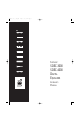
User Guide


5
0
1
2
3
4
5
6
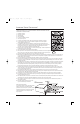
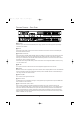
DETAILED DIAGRAM –FRONT PANEL
0 INPUT/OUTPUT CARD MONITORING
Each channel has three LED indicators showing:
C
LIP
Illuminated – Indicates clipping in the analog domain for each channel of the fitted Input or Output card.
The LED will light at +18.5dB.
S
IGNAL
Illuminated – The Signal LED will light for each channel of a fitted Input or Output card when the signal
reaches or exceeds the signal threshold of –20dB.
PHANTOM
This feature is currently not supported by JBL Synthesis (lights to indicate +48V phantom power has
been activated for the relevant channel of a fitted input card).
1 USB
This is currently for future use and is not supported.
2 DATA ACTIVITY
The Data Activity LED will flash to indicate that the device is communicating with another control device, either
on the network or via the USB, serial or control ports.
3 NETWORK LINK
The Network Link indicates the presence of Cat. 5 Ethernet cables. If no cables are connected, the LED is unlit;
the LED flashes if either a control or CobraNet
®
cable is fitted, and remains illuminated if both cables are connected.
The network link is used for configuring and calibrating the Synthesis System when using the DACS calibration,
and for system status when using the SDEC-4000.
4 LCD (LIQUID CRYSTAL DISPLAY)
Indicates the name/ID and IP address of the unit.
5 CONTRAST (HOLD)
Pressing and holding the Locate switch will cycle the LCD through its contrast range.
6 LOCATE
Pressing the Locate switch on the front of the unit will illuminate the Locate switch on the rear and identify the
device within the DACS software.
SDEC3000.4000.om.qxd 11/8/06 4:06 PM Page 5