SMS1 Soundzone Music System For Business Music Preliminary Owners Manual
These products are in compliance with the EMC Directive 89/ 336/EEC and Article 10 (1) of the directive. In compliance with Technical Regulations EN50081-1 and EN50082-1. For a copy of the model-specific CE Declaration of Conformity, contact JBL at the address listed at the end of this manual.
Table of Contents Quick Start Guide . . . . . . . . . . . . . . . 1 Introduction . . . . . . . . . . . . . . . . . 2 Components and Parts . . . . . . . . . . . . 3 Installation . . . . . . . . . . . . . . . . . . 7 Placement . . . . . . . . . . . . . . . . . . 7 Coverage . . . . . . . . . . . . . . . . . . 8 Satellites . . . . . . . . . . . . . . . . . . . 8 Subwoofer . . . . . . . . . . . . . . . 9 Wall Mounting . . . . . . . . . . . . . 10 Floor Placement . . . . . . . . . . . .
Quick Start Guide The Following is a set of steps that will get the SMS1 Business Music System up and playing quickly. For more detailed descriptions, explanations, and setup, please read the rest of this manual. After each step, the section that covers the step in more detail noted in Italics. Step 1 – Remove the subwoofer cabinet from the wall baffle by removing the screws from all of the mounting tabs. Be sure to disconnect the subwoofer driver cable.
Introduction Thank you for purchasing the SMS1 Soundzone Business Music System. The SMS1 is an all-in-one solution for businesses that require high quality sound with a minimum of complexity, and a minimum price. Businesses all around the world are becoming increasingly aware of the positive effect music can have on customers. The overall experience offered by a business is becoming the most important part of capturing the attention of consumers, even more than the actual product or service that is offered.
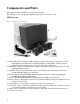
Components and Parts Please take a moment to familiarize yourself with all of the parts. This will help you as you progress through the manual, and as you set up the system. SMS1-System Figure 1 – SMS1 System Components 1 - SMS1-SUB - This is the Subwoofer Module. It houses the Low Frequency Loudspeaker, one 120 Watt amplifier for the Subwoofer, two 20 Watt amplifiers for the Satellites, and the Soundzone Electronics. Please see Figure 2 for more detail on the Subwoofer Module.
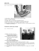
SMS1-SUB This section gives detail of the parts of the Subwoofer Module. Figure 2 – Subwoofer Cabinet 1 - Cabinet Chassis – This is the main body of the low frequency cabinet. 2 - Driver – Low frequency Element 3 - Port Tube – This is one of the primary sound radiation locations. 4 - Grille Trim – These pieces go on after installation to trim and protect the module. 5 - Subwoofer Leads -These connect to the Electronic Module Subwoofer output.
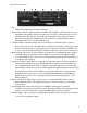
Control Panel and Connector Panel Figure 4a: Control Panel 1 - Power Switch – Use this switch to turn the System on and off. 2 - Power LED – This LED illuminates when the Power is ON. 3 - Security Panel Attachment Points – The INCLUDED Security Panel is attached here using the INCLUDED screws and standoffs. This panel covers the trim controls to prevent unauthorized tampering . 4 - Input CH Polarity Switch – This switch changes the polarity of the input to the Subwoofer.
Figure 4b: Connector Panel 1 - Paging Microphone Input – This is the Connection for a Paging Microphone. It is designed for a balanced low impedance microphone audio input. 2 - Phantom Power Switch – When the Switch is pushed in ON, the SMS1 sends Phantom Power to the Paging Microphone. Phantom Power is required if you are using a condenser microphone. Leave the switch in the OFF, outward, position if the mic works in this position.
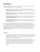
Installation Installing the SMS1 Business music system can be quick and easy if the steps in this manual are followed closely. The method for installation covers four main elements: Placement – This section covers the basics of Loudspeaker Placement. Ideas and concepts pertaining to coverage and balance of sound are covered here. This section also deals with aesthetic and architectural issues with the placement of speakers.
Coverage The SMS1 System has been designed to cover up to 2500 square feet of space (225m2) with a reasonable background sound level. As the space gets smaller, the SMS1 will provide higher overall levels. If the space is larger than 2500 ft2, then more speakers or systems may be necessary. This manual will go over actual physical placement of the components based on a rectangular room of approximately 2500 ft2. Satellites The Satellites are generally easy to place.
Subwoofer The SMS1 System consists of a single Subwoofer for each four Satellites. In a room of 2500-ft2 or less, one subwoofer may be capable of “filling” the room with bass. However, regardless of the subwoofer’s design, there will be more sound close to the Subwoofer and less sound further away. The best case is to be able to place the Subwoofer in an area where people will generally not be, and essentially the same distance away from all the places that people typically will be.
Wall Mounting Both the Subwoofer and the Satellites arrive ready for wall mounting. The Subwoofer cabinet must first be separated from the wall baffle. To do this, simply remove the screws from all the mounting tabs. Then pull the cabinet off of the baffle. Be sure to disconnect the cables attaching the subwoofer driver to the electronics as soon as the cable is accessible.
Remember that power and audio input signal need to come in through the wall baffle, and speaker signal needs to go out through the Baffle, to the satellites. Be sure that there is necessary clearance for these requirements. Installation and Hookup of the Subwoofer The following is a step by step guide for installing the Subwoofer on a wall. NOTE: The instructions below are for walls with wooden studs.
Step 4: Punchout any knockouts in the Wall Baffle you plan to use, or remove either of the plates from the wall baffle as necessary. Pull any loose wires or cords through the chosen path and place the baffle against the wall lined up with the predrilled holes. Screw the Wall Baffle into place. Step 5: Make all connections, but do not turn on the Subwoofer. - Connect the IEC Power Cord to the Electronic Module at the IEC Power Cord Jack. - Plug the other end of the power cord into the grounded power socket.
NOTE: CONNECT TO ONLY ONE LEFT/RIGHT INPUT Step 6: Bring the Subwoofer cabinet to the wall baffle. Connect the Subwoofer Driver Leads from the cabinet to the Low Frequency Driver Wires from the Module. Figure 8: Connecting the Subwoofer Driver Step 7: Place the Subwoofer cabinet onto the Wall Baffle. The mounting tabs should all be lined up. Hold the Cabinet in place until screws are placed and tightened. It is important the cabinet be oriented in its intended upright position.
Step 8: Place the Punched-metal Grille Trim pieces in their correct position and begin screwing the provided screws through the grille, into the mounting tabs. If the Subwoofer is to be used on a floor or shelf, follow steps 5 through 8 above. Then attach the INCLUDED Feet to the back of the Wall Baffle at the bottom, using the provided screws. Set the Subwoofer in place. You might need to physically attach the subwoofer to the ground or shelf to secure it in place.
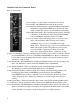
Step 5: Remove the logo badge from the SMS1-SAT, insert the INCLUDED 3mm hex key, loosen the InvisiBall clamp by turning the hex key counter-clockwise and place the InvisiBall Receptacle over the Ball. Step 6: Turn the hex key CLOCKWISE until the mechanism begins to clamp down on the InvisiBall. Step 7: Before the mechanism is fully tightened, aim the SMS1-SAT on the ball. Then tighten the mechanism until it holds the speaker in place. Step 8: Replace the Logo Badge on the front of the Satellite.
Tuning With the SMS1-SUB installed, the Control Panel on the side of the SMS1-SUB is still entirely accessible. The next section of this manual will go through a step by step process to properly setup and tune the SMS1 System. Step 1: With the Power off, turn the Volume Knob, and Paging Mic Volume Knob down (COUNTER-CLOCKWISE). With a small Flathead screwdriver turn the Page Sensitivity and Subwoofer Trim Knobs to the 12:00 Center Position. Turn the Auto Warmth Trim Knob to off (COUNTER-CLOCKWISE).
Step 6: If using a Paging Microphone, GRADUALLY turn the Paging Mic Volume Knob CLOCKWISE while pressing the Push-To-Talk switch and speaking into the Microphone. Adjust the level until the voice is clear and intelligible, but before the system feeds back. If the Push-To-Talk switch is not resulting a reduced music level, and an audible voice signal, turn the Page Sensitivity Trim Knob CLOCKWISE until the music “Ducks” out of the way of the Page.
Additional Applications While the primary configuration of the SMS1 System is the SMS1-SUB and four SMS1-SAT’s in a single setup, there are various ways to use the SMS1 Components. Note, however, that the SMS1-SAT’s should only be used in conjunction with the SMS1-SUB. Driving Other Satellites. The SMS1-SUB can drive any loudspeakers that are rated at 8 Ohms or higher and which can be adequately powered from 10 Watts per speaker.
Specifications POWER CAPABILITY SMS1-Sub: SMS1-Sat: SPL Capability (1W, 1m): SMS1-Sub: SMS1-Sat: INPUTS Music (use only one of the following): Microphone: Internal Crossover: Remote Volume Control Jack: SETTINGS Protected Controls Subwoofer Polarity: Crossover: Bass Trim: AutoWarmth: Page Threshold: Speaker EQ: User Accessible Controls: Music: Mic: MODELS: SMS1 SMS1-WH SMS1/230 SMS1-WH/230 SMS1-SUB SMS1-SUB-WH SMS1-SUB/230 SMS1-SUB-WH/230 OPTIONAL ACCESSORIES: Z-M1 Paging Microphone: ZR-V Remote Wallp
Warranty & Contacting JBL These products are designed and backed by JBL Professional, the world leader in sound reinforcement. For complete JBL warranty information, to order replacement parts or to ask for clarifications to this manual, contact JBL Professional: WITHIN THE UNITED STATES Contact: Applications Department JBL Professional PO Box 2200 8500 Balboa Boulevard Northridge CA 91329 USA. In the USA you may call Monday through Fiday 8:00 am to 5:00 pm Pacific Coast Time (818) 894-8850.
JBL Professional 8500 Balboa Blvd, P.O. Box 2200 Northridge, CA 91329 U.S.A.