Welcome and Thank You ....................................................I Product Description ...........................................................2 The lnvisiBallTMMounting System ..............................3-4 Connections, Polarity, etc. ...........................................5-6 Sound Indoors .................................................................7-8 Sound Outdoors ............................................................9-10 Painting the Speakers .............................
Control@23, Control@25, Control@28 Control@23, Control@25, Control@28 Control@23, Control@25, Control@28 These full range models of the ControP Series for contractors are designed for a wide variely of applications,be 11outdoors, indoors, painted to match decor, stacked together, or arrayed s~de-by-side.Optional cluster mounting brackets and distribut~on transformers enhance commercial value to the series, and further demonstrate JBL Professional'ssupporl of sound contractors.
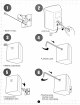
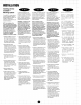
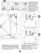
-AA-"u """""* MOUNT TO WALL LOOSEN CLAMP L - -- * REMOVE LOGO BADGE K w 7@ ATTACH SAFETY CORDIMOUNT SPKR POSITION SPKR, TIGHTEN CLAMP.
INSTALLATION Installing with the InvisiBall TM Mounting System - The InvisiBalfMis a unique method of mounting a loudspeaker. Patents are pending worldwide on this design. The lnvisiBalfMis designed to be unobtrusive, offer theft deterrence, and simplify the installers job. NOTE: Your installation of this Commercial Sound Solution must be done in conformity with local building codes.
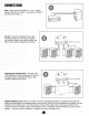
Input - Simply connect the amplifier's "+"and "-" outputs directly to the red (+) and black (-) input jacks on the back of the enclosure (see diag. 1). - Since the loudspeakers have a rated ce of 8R each, more than one speaker usually be wired to one amplifier channel (see See "amplifier impedance load" below.) MPLlFlER 4R PER CHANNEL n EACH CHANNEL ating the Subwoofer SB-2 - Treat each input Subwoofer as an 8R loudspeaker and wire into lete system accordingly (see diag. 3).
INPUT LEFT RIGHT AMPLIFIER 4Cl PER CHANNEL 6.n EACH CHANNEL -- SerieslParallel - It is possible to utilize various serieslparallel 'hook-up' topologies to increase the number of loudspea driven on an amplifier. See diag. 4 for one example of a serieslparallel hook-up topology. Note: Mismatching the speaker impedance such that it is below the minimum impedance rating of an amplifier channel damage the amplifier and degrade performance.
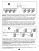
because of differences in the acoustical setting. Since an enclosed room presents acoustical boundaries (walls, floors & ceilings), sound indoors exhibits quite complex behavior. Each time a sound wave strikes a boundary, part of the wave's energy is reflected and part is absorbed (see diag. 1). Reflection & absorption are dependent on the freauencv of the sound wave ' and the angle at which it strikes the boundary.
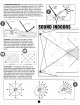
HORIZONTAL frequencies go where you point them. Simply aim the center axis of the speaker into the plane slightly above the listening area. The 90" x 90" horns of the Control@Contractor Series disperse the high notes by 45" off axis in every direction. For large or unusually shaped rooms, divide the area into zones and let the horn patterns dictate the spacing between the speakers (see diag.
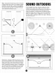
Wind - Wind gives the illusion that a sound is coming from a different direction than it really is. This creates a re<ant propagation vector (see diag. 1). When sound propagates with the wind it tends to refract downward, and against the wind refract upwards (see diag. 2), (*refraction is the term used to describe the bending of sound). ISS WlND PROPAGATION VECTOR CROSS WlND ' CROSS WlND Temperature - Temperature differences also have a small effect'on sound propagation.
It is important to understand that just as the propagation of sound outdoors is effected by its surroundings so is the propagation of sound indoors. Some of these environmental factors exist in both cases, such as reflective surfaces and absorbant materials, but there are a few unique effects that may need to be considered. The factors described on this Daae can cause the behavior of an outdoor installation to deviate from tjhe Inverse Square Law.
RODUCT CARE MAINTENANCE A Your Control Contractor system has been designed and manufactured for durability and reliable service. As with any fine product, proper maintenance and care will extend the life of your system. A You can expect your system components to perform indefinitely if you use them within their stated limits for power handling, and see that they are not abused. Always protect the loudspeakers from over-excursion caused by strong subsonic signals (signals below 30Hz).
If none of the suggestions below solve your problem, contact your nearest JBL service center or JBL distributor. Problem 1. No Output. Possible Causekl """" Action Speaker Cable(s) Replace the cable(s) connecting the loudspeaker system and amplifier. Amplifier Make sure the amplifier channel is being fed an input signal (preferably via a "signal input" indicator on th amp). Check that the amplifier channel's volume control is turned up.
Frequency Range: Power Capacity: &flsf~ity: 87dB 1W, l m Nominal lmpedam: 8R Crossover Frequency: 3.5kHz EnclosureMaterial: HIPS (hgh impact polystyrene) Termination: Spring clips (adaptedto accept dual banana plugs) Dimensions(HxWxD): 188 x 138 x 108mm (7.5 x 5.5 x 4.3in) Net WeigM (each): 1.8kg (4 Ibs) ShippingWeight (pair): 4.1 kg (9 Ibs) Environmentat Conformsto Mil Std. 202F. Method 101D.