
- JBM Electronics Cables for Gateway User's Manual

Cables for Gateway 20 through 21 PAGE 3
© JBM Electronics Co. 1-800-489-7781 www.jbmelectronics.com
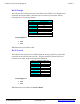
9F to 9M/F (DCE)
This table lists the required RS-232 wiring required to provide a DCE interface for a
Gateway Comm. Port. The pins should be connected from one connector to the other
using the transpositions indicated. This cable is used for modem emulation.
Units Supported
• C20
JBM Electronics Part Number: C/9SF-9M-DCE-6’
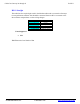
9F to 25M/F
(DCE)
This table lists the required RS-232 wiring required to provide a DCE interface for a
Gateway Comm. Port. The pins should be connected from one connector to the other
using the transpositions indicated. This cable is used for modem emulation.
Units Supported
• C20
JBM Electronics Part Number: C/9SF-25M-DCE-6’
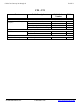
9-Pin Female to 9-Pin Male
To JBM Device
DIRECTION
To Async Device
1 tied to 6
Å
4
2
Å
3
3
Æ
2
4
Æ
6 tied to 8
5 GND 5
- - -
7
Æ
1
8
Å
7
- - -
Converts Com Port to DCE
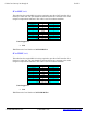
9-PIN FEMALE TO 25-PIN MALE
JBM Device
DIRECTION
Async Device
1 tied to 6
Å
20
2
Å
2
3
Æ
3
4
Æ
5 tied to 6
5 GND 7
- - -
7
Æ
8
8
Å
4
- -
Converts Com Port to DCE