". Dear Penney Customer: The product you purchased has been carefully engineered and manufactured to give you dependable operation.However, like all mechanical products, your machine will occasionally require adjustment and maintenance. This handbook should be read before operating or performing any adjustments on your machine. Should you require technical assistance, please contact the nearest JCPenney retailstore, product service center, or catarog center.
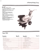
. JCPenney Rotary Tiller JCPenney Catalog No. 811-0843 Engine: B & S, 8 H.P., 319 cc, 4-cycle with an easy spin recoH starter power protection. Tines: 16 hardened slasher tines mounted on a 1 y. " tine shaft with a tilling width of 26". Drive: Two step chain reduction sealed case. Four speed forward with power reverse. in a drive Control: The drive control and throttle are located on the handle panel. Wheels: 10 x 2.75 inches semi-pneumatic tires with steel rims. Adjustable wheel height.
Safety Rules IMPORTANT It is suggested that this manual be read in its entirety before attempting to assemble or operate. Keep this manual in a safe place for future reference and for ordering replacement parts. operating section of this manual for proper fuel and amount. Your tiller is a precision piece of powerequipment, not a play thing. Therefore,exercise extreme caution at all times. This unit is shipped WITHOUT GASOLINE or OIL.
Rotary Optiona Furrow Equipment opener can be attached to the depth bar to lay open a furrOV'J for planting. It also used as a hiller for planting potatoes. ;;;;;~~~ Features ~ Opener Model 3004 Catalog No.
Hintsfor Best Performance Your power drive train is comprised of a variable speed pulley with four forward speeds, reverse, and a two step, double chain, reduction to thetines. The 1 Y4inch tine shaft is supported by two self-lubricating bronze bearings. The 16 hardened tines will handle the toughest of gardening tasks. Ten inch by 2.75 inch rib tread tires support the back of the tiller. The rear wheel height is adjustable for greater versatility.
Hintsfor ~ Depth ~ Best Performance First "walk" the tiller over to the work area. To do this, lock the depth bar out of the way, set the throttle in the slow position, place the control lever in the forward position and maintain a light upward pressure on the handles. Your tiller will "walk" over the top of theground without the tines entering thesoil. Forward . SIOW",,~ Pos ~ Bar Up If the garden is turned over in the Fall, the soil should be finely pulverized in the Spring.
Hints for Best Performance Plants such as grass, with shallow roots, need only two to four inches tilled soil whereas plants with a deep root system should have a deeply tilledbed. Till the soil as soon as it is workable in the Spring. You can till to a maximum depth of six to eight inches. When preparing a yard for a lawn, the soil should be leveled so it is well drained and free from high spots.
. 1 Assembly The tiller. except the handle, throttle control, wheels, tine assemblies and controls, is fully assembled, packed and shipped in one container. Depth Bar 1 Remove the tiller and all parts from the carton. Make certain that all loose parts and literature have been removed before the carton is discarded. 2 Attach the depth bar to the tailpiece with the clevis pin and spring pin. (See fi~ure 1.) Figure 1 Tine Assembly Place the first outer tine assemb.
1 3 Figure Assembly Handle Assembly Assemble the handle to the handle brackets with the four hex head cap screws 3/8-16 x 1" long, lockwashers 3/8" and hex locknuts 3/8-16. (See figure 3.)2 Assemble the grips to the handle. (Soaking the grips in hot water will aid assembly.) Figure 3 Place the control rod throught he control panel on the upper handle and screw the threaded end of the control rod into the ferrule on the "L" bracket on the left side of the chain case.
Assembly Controls Caution: If the belt cover (see page 3) is removed, you will not have any neutral. This belt cover contains the belt trapout around the engine pulley. The control rod must be assembled exactly as shown in the assembly instructions or you will not have a neutral. Note: For ease of assembly place the control lever in the number one position when installing the belt cover. (See figure 7.
The Figure Operation A Read and Heed Safety Rules on page 2. See Engine operating section forspecific engine Instructions. Throttle Control The throttle control is located on the handle panel. This regulates the engine speed and shuts off the engine. Move the lever forward to increase the engine speed. Move the lever back to slow down and stop the engine. The tiller should be operated with the throttle in the fast position. (See figure 9.
11 Operation Depth Bar The depth bar is used to retard the forward speed the ground and The farther the the ground the (See figure 11.), of the tiller across set the tilling depth. depth bar goes into deeper you will till. Figure 11 Wheel Adjustment The wheel height can be adjusted by removing the long clevis pin on the wheel hanger and raising or lowering the position of the wheel hanger. The higher the setting the deeper the tilling depth. (See figure 11.
Maintenance Warning: If any adjustments are made to the engine while the engine is running (e.g. carburetor) disengage the clutch. Keep clear of all moving parts and be careful of heated surfaces and the muffler.
Maintenance Replacing the Belt 4 Remove the belts from the variable speed pulley. It is not necessary to remove the belt guard on the variable speed pulley. (See figure 15.J 5 Reassemble with the new belts. 6 Replace the belt cover. Caution: You do not have a neutral in your tiller if the belt cover is removed. Install the belt cover before testing. 14 Figure 15 Troubleshooting Off-season Figure Referto WARNING: Storage the chart on page 14.
Problem Engine 2 3 fails to Hard starting of power Operation Cause start or 10SI; A Fill tank if empty B Connect lead wire C Move throttle position. 0 Spark should jump gap between control electrode and side electrode. If spark does not jump, replace the spark plug. Remove spark plug, dry the plug, crank engine with plug removed, and throttle in off position. Replace spark plug and lead wire and resume starting procedures. Drain tank and refill with fresh gasoline.
8 efore B ~ 1 Note: 2 H.P. Model 190402-1835-02 In the interest of Safety, Do Not run Engine at excessive Operating injury. an engine at excessive speeds Increases speeds. the hazard of personal Do not tamper with parts which ma'; Increase the governed Dirt and other debris in cooling fins or governor speed. See cleaning instructions, page 18. speed.
1 l-- Starting The Engine Open Fuel Valve. The fuel valve is located under the gasoline tank and should be turned counter-clockwise to open. To clean the fuel filter. loosen thumb screw below filter bowl. Remove and clean filter bowl and screen. Open shut-off valve to see if fuel flows freely from the tank. If you find a gummy. varnish-like substance use alcohol or acetone to dissolve it. ~ / 2 Set the Throttle Move the throttle control on the upper handle Into position.
Engine Operating Engine Maintenance 1 and Maintenance I nst ructions Check Oil Level Regularlyat least after every 5 hours of operation. Check the dip stick and maintain the oil between the ADD and FULL marks. Change oil after first 5 hours of operation. Thereafter change oil every 25 hours of operation. Remove the drain plug and drain the oil while the engine is warm. Refill with new oil of proper grade (approximately 23/4 pints). Replace oil minder. 2 3 Air Filter.
Engine 4 Maintenance Clean Cooling System Grass or chaff may clog cooling system after prolonged service. Continued operation with a clogged cooling system causes severe overheating and possible engine damage. Remove blower housing and clean regularly. ~ ~ Ir:===; 9, ({J ,-J , '==""'/ -~4d~[=.ifL. 5 Spark Plug Clean and reset gap at .030" every 100 hours of operation. Caution: Blast cleaning of spark plugs in machines that use abrasive grit is not recommended.