RADIOBAND SYSTEM INSTALLATION MANUAL RADIOBAND SYSTEM INSTALLATION MANUAL V2.2 / 1 JCM TECHNOLOGIES S.A.
CONTENTS CONTENTS ...................................................................................................................... 2 1. INTRODUCTION ......................................................................................................... 3 1.1 System description ............................................................................................... 3 1.2 Normative requirements ...................................................................................... 3 2.
1. INTRODUCTION 1.1 System description The Radioband system is designed for installation with a safety edge in garage door installations. This system allows for wireless safety edge – control panel connection. To install this system, you must follow the advice included in this manual and take the requirements of the applicable normative into account. 1.
JCM TECHNOLOGIES, S.A. declares herewith that the product RADIOBAND/T, RADIOBAND/R, RADIOBAND/RC-RCS complies with the relevant fundamental requirements as per Article 3 of the R&TTE Directive 1999/5/EG, insofar as the product is used correctly. This device complies with Part 15 of the FCC Rules.
The Radioband system is in line with the Machines Directive under EN 954-1, Category 2. RADIOBAND SYSTEM INSTALLATION MANUAL V2.2 / 5 JCM TECHNOLOGIES S.A.
2. THE SYSTEM 2.1 RADIOBAND/T Operating frequency Power supply Op. consumption Radiated power Op. temperature Seal Dimensions Range (guaranteed) Battery life Minimum time between two RADIOBAND/T activations (for complying with the R&TTE Directive) 868.90MHz 3V DC (2 x 1.5V LR03 AAA) 12mA < 25mW -20ºC - +55ºC IP67 85 x 53 x 36mm 10m 2 years 7 min RADIOBAND SYSTEM INSTALLATION MANUAL V2.2 / 6 JCM TECHNOLOGIES S.A.
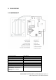
INSTALLATION AND CONNECTIONS Fix the back of the box to the door. Install the transmitter following the technical manual and avoid placing metallic surfaces between the receiver and the transmitter. Pass the cables through the bottom of the transmitter. Connect a resistive 8K2 safety band directly to terminal B1 and ensure that the safety edge keeps totally waterproof. Fix the front of the transmitter to the back with the screws supplied for the purpose. N.B.
INSTALLATION ADVICE Install the equipment so that the cable outlet is at the bottom In installations likely to have range problems between the transmitter and the receiver, the antenna must stand vertically from the hole in the gland Do not fit the equipment at ground level Do not place metal surfaces between the transmitter and the receiver The transmitter and receiver antenna must be parallel to each other for optimum signal reception * Once the system has been installed, check it works correctly by
2.2 RADIOBAND/R Frequency Memory Number of relays Power supply Power supply range Relay contacts Consumption: idle/op. Self-test input Power Op. temperature Seal Box size Range (guaranteed) 868.90MHz 6 Radioband-T (3 on relay 1, 3 on relay 2) 2 relays 12/24V AC/DC 9-35V DC 8-28V AC 1A 18mA/80mA 2 0/12/24V AC/DC inputs with selectable polarity < 25mW -20ºC to +85ºC IP54 (with IP65 cable seals) 82 x 190 x 40mm 10 metres RADIOBAND SYSTEM INSTALLATION MANUAL V2.2 / 9 JCM TECHNOLOGIES S.A.
INSTALLATION AND CONNECTIONS Fix the back of the box to the wall, using the wall plugs and screws supplied. Install the receiver, close to the door and avoid metal surfaces between the receiver and the transmitter. Pass the cables through the bottom of the receiver. Connect the power cables to the terminals of the printed circuit, following the indications of the connections diagram. Store RADIOBAND-T. Fix the front of the receiver to the back with the screws supplied for the purpose.
LIGHT INDICATORS RADIOBAND/R- In operation RC-RCS Relay 1 LED Normally off. Indicates the status of the relay output. If R1 is not connected, on. Relay 2 LED Normally off. Indicates the status of the relay output. If R2 is not connected, on. In programming On. Indicates the channel to be programmed. On. Indicates the channel to be programmed. OPERATION The receiver checks that all the programmed bands are working properly.
DETECTION OF BAND FAILURE If the communication with a RADIOBAND/T fails during checking, or the communication is deficient (for instance, too many communication retries or poor coverage), the RADIOBAND/R emits three consecutive beeps, indicating that an error has occurred. Halt the door manoeuvre and press the safety bands installed to detect what has failed. - If a single beep is heard on pressing a band, this means that the band is correct.
INSTALLATION ADVICE The transmitter and receiver antenna must be parallel to each other for optimum signal reception Do not fit the equipment at ground level Do not place metal surfaces between the transmitter and the receiver The transmitter and receiver antenna must be parallel to each other for optimum signal reception RADIOBAND SYSTEM INSTALLATION MANUAL V2.2 / 13 JCM TECHNOLOGIES S.A.
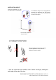
a) Connection to safety edge inlet b) Connection to security contact inlet RADIOBAND SYSTEM INSTALLATION MANUAL V2.2 / 14 JCM TECHNOLOGIES S.A.
c) Auto-test connection with negative polarisation d) Auto-test connection with positive polarisation * Once the system has been installed, check it works correctly by enabling the safety edge on the ends of the door. RADIOBAND SYSTEM INSTALLATION MANUAL V2.2 / 15 JCM TECHNOLOGIES S.A.
2.3 RADIOBAND/RC-RCS Frequency Memory Power supply Power supply range Consumption: idle/op. Self-test input Power Op. temperature Seal Box size Range (guaranteed) 868.90MHz 6 Radioband-T pluggable --18mA incorporated < 25mW -20ºC to +85ºC IP20 50x20x17mm 10 metres RADIOBAND SYSTEM INSTALLATION MANUAL V2.2 / 16 JCM TECHNOLOGIES S.A.
INSTALLATION AND CONNECTIONS Connection to a control panel using a connector for safety devices. LIGHT INDICATORS RADIOBAND/R- In operation RC-RCS Relay 1 LED Normally off. Indicates the status of the relay output. If R1 is not connected, on. Relay 2 LED Normally off. Indicates the status of the relay output. If R2 is not connected, on. In programming On. Indicates the channel to be programmed. On. Indicates the channel to be programmed.
RADIOBAND/RC-RCS will exit checking automatically, indicating with two beeps that the check has been correct. The check indicator light will go out. DETECTION OF BAND FAILURE If the communication with a RADIOBAND/T fails during checking, or the communication is deficient (for instance, too many communication retries or poor coverage), the RADIOBAND/RC-RCS emits three consecutive beeps, indicating that an error has occurred.
INSTALLATION ADVICE An AED-868 or FLAT 868 antenna extension to 868 MHz should be installed for greater range Where an antenna extension is not installed, place the receiver card antenna in vertical position 868MHz AED-868 or FLAT 868 antenna extension with RG 58 coaxial cable * Once the system has been installed, check it works correctly by enabling the safety edge on the ends of the door. RADIOBAND SYSTEM INSTALLATION MANUAL V2.2 / 19 JCM TECHNOLOGIES S.A.
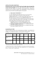
2.4 COMPATIBILITY TABLE RADIOBAND/T (A) RADIOBAND/T (B) RADIOBAND/R-RC-RCS (C) No check function No check function RADIOBAND/R-RC-RCS (D) No check function With check function A: model without outdoor antenna (WBAND-Ba board) B: model with outdoor antenna (WBAND-Bb board and later) C: model without CHECK button (/R WBAND-Ia to WBAND-Id board; /RC-RCS WBANDQa and WBAND-Qb board) D: model with CHECK button (/R WBAND-Ie board and later; /RC-RCS WBAND-Qc board and later) N.B.
3. AUTO-TEST FUNCTION 3.1 AUTO-TEST DESCRIPTION Before starting operations, the control panel must check that the entire security system is working correctly. To make this check, the panel must act on the auto-test signal.
Switching the status of the output relay outlet means that the control status and the correct working order of the RADIOBAND/R output relays can be checked. Description Tauto-test TMAXauto-test Tend Ttype 375ms Tmin 10ms Tmax 750ms 1500ms 50 ms 3.
4. RADIOBAND SYSTEM INSTALLATION RECOMMENDATIONS 4.1 Installation on roller door with control panel and RADIOBAND/R. 4.2 Installation on two-leafed swing door with control panel and RADIOBAND/RC-RCS. RADIOBAND SYSTEM INSTALLATION MANUAL V2.2 / 23 JCM TECHNOLOGIES S.A.
4.3 Installation on horizontal sectional door with control panel and RADIOBAND/R. 4.4. Installation on angled sectional door with control panel and RADIOBAND/R. RADIOBAND SYSTEM INSTALLATION MANUAL V2.2 / 24 JCM TECHNOLOGIES S.A.
4.5 Installation on stackable sectional door with control panel and RADIOBAND/R. 4.6 Installation on one-leafed residential folding door with control panel with RADIOBAND/RC-RCS card connector. M RADIOBAND SYSTEM INSTALLATION MANUAL V2.2 / 25 JCM TECHNOLOGIES S.A.
4.7 Installation on one-leafed folding door for communities with control panel and RADIOBAND/R. 4.8 Installation on one-leafed sliding door with control panel and RADIOBAND/R. M RADIOBAND SYSTEM INSTALLATION MANUAL V2.2 / 26 JCM TECHNOLOGIES S.A.
4.9 Installation on sliding door RADIOBAND/RC-RCS card connector. with control panel and M 4.10 Installation on guillotine door with control panel and RADIOBAND/R. RADIOBAND SYSTEM INSTALLATION MANUAL V2.2 / 27 JCM TECHNOLOGIES S.A.
5. JCM CONTROL PANEL DIAGRAM FOR CONNECTION TO THE RADIOBAND SYSTEM SINGLE-PHASE PANELS JCM Control panels START-EU Applications Description Roller for residential and commercial use RESIDENT+DCS Roller for residential use ROLLERMOTION Roller for residential and commercial use BASIC-EU Sliding for residential and community use MAIN-1T-EU Swing, folding and sliding for residential and community use Semi-automatic operations. 433 or 868 MHz radio card connection.
ADVANCE STANDARD-1TEU STANDARD-2TEU Swing, folding and sliding for residential and intensive use. Semi-automatic and automatic operations. Digital programming. Gentle stop. RADIOBAND and other force limiting device (FORCELIMIT and T-HALL) connector. 433 or 868 MHz card connector. Start and stop button connection. Limit switch, Limit switch, safety edge and security contact connection. Electro-lock connection. Traffic light card or signal card connector. Garage light contact 24Vac outlet Autotest outlet.
D.C. PANELS JCM Control panels CONTINUE-EU Applications Description Sectional, swing, folding and sliding for residential and community use Semi-automatic and automatic operations by limit switch or with Hall sensor. Time control. Electronic motor power limitation without the need for additional devices. 433 or 868 MHz radio card connector. Start and stop button connection. Limit switch, safety edge and security contact connection. Garage light contact.
TRIBASIC-S/I TRIBASIC-IND INDUSTRIALMAN INDUSTRIAL-EU TRI-ADVANCE Same as TRIBASIC Same as TRIBASIC without ON/OFF switch. Auto-test outlet. Same as Same as TRIBASIC but in TRIBASIC INDUSTRIAL box. Autotest outlet. Swing for “Dead-man” operations industrial use 433 or 868 MHz radio card connector. Open, start and stop button connection. Limit switch connection. Signal or traffic light card connector. Garage light contact 24Vac outlet Electro-lock connection.