
Installation Instructions
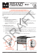

Miller Edge, Inc. • www.milleredge.com • info@milleredge.com • East Coast: 800-220-4422 • West Coast: 800-887-3343
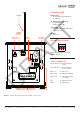
IMAGE 3. RBand Edge Transmitter PCB & Connections
3. TRANSMITTER: PROGRAM MODE
3-1. Confirm the Receiver is powered up. Prior to mounting the Transmitter, remove the cover and insert the
batteries, noting their polarity [IMAGE 3]. The green LED should blink to indicate that the Transmitter has
not been associated with the Receiver yet.
3-2.
To enter learn mode, press and hold the Receiver program button [IMAGE 2] for ~2 seconds until the R1
LED turns on, then release the button.
3-3.
Press the Transmitter program button [IMAGE 3] for ~2 seconds. The Receiver should beep. Wait 10
seconds for an additional beep to indicate that programming is complete.
3-4.
Repeat 3-2 and 3-3 for up to 3 Transmitters.
4. TRANSMITTER: INSTALL & TEST
4-1. Strip back approximately 2 inches of outer covering of sensing edge cable, then feed through the Transmitter
strain relief fitting [IMAGE 3]. Connect the two sensing edge wires to the removable terminal. Dress the
wires with a small service loop and tighten the strain relief. Mount unit utilizing the mounting holes at the 4
corners of the Transmitter box. Return lid to Transmitter, noting the alignment pin [IMAGE 3].
4-2.
Test the sensing edge for functionality: press the sensing edge and the Receiver R1 LED will turn on.
5. TROUBLESHOOTING
If the Receiver does not react to the Transmitter, you can check the RF signal strength:
5-1.
Press the check button on the Receiver for ~2 seconds [IMAGE 2]; 4 beeps will be heard. You then will hear
a beep every 1-1/2 seconds during the check process. Wait about 30 seconds; if no other beeps occur, your
system is functioning. 3 quick beeps indicates a communication error.
5-2.
Activate the sensing edge and observe the check LED; 3-5 flashes is ideal. Less than 3 flashes means
there is a weak signal.
5-3. To exit check function, press the check button again, or the system will time-out after 5 minutes. There will
be a series of beeps heard upon exiting.
6. ERASING THE RECEIVER
Erase the Receiver if you need to replace a Transmitter or you have any other programming problems:
6-1.
Use a screwdriver to short the two pins next to the DIP switch marked MR [IMAGE 2].
6-2. While shorting the pins, press and hold the program button for several seconds; you will hear a series of 10
beeps following by a rapid chirping sound.
6-3. When the chirping stops, release the program button. Wait ~10 seconds and you will hear 2 beeps. The
Receiver is now ready to be reprogrammed.
PROGRAM BUTTON
REMOVABLE
SENSING EDGE
TERMINAL BLOCK
(4) CORNER
MOUNTING HOLES
GREEN LED
ALIGNMENT PIN
STRAIN RELIEF FITTING
ALIGNMENT PIN
(2) 3.6V AA LITHIUM
BATTERIES
DRAFT