
User's Manual


1248xxx_Rev0.0 RB3 OSE916 Page 2/4
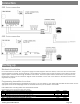
Connection
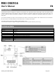
OSE 3 wire connection
OSE 2 wire connection
Starting up
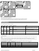
Mechanical installation
Fix the back of the box to the wall, using the wall plugs and screws supplied. Install the receiver, close to the door and avoid metal
surfaces between the receiver and the transmitter. The transmitter and receiver antenna must be parallel to each other for optimum
signal reception. Pass the cables through the bottom of the receiver. Connect the power cables to the terminals of the printed circuit,
following the indications of the connections diagram. Store transmitters. Fix the front of the receiver to the back with the screws
supplied for the purpose.
Programming transmitter to receiver
The receiver allows programming 6 transmitters (3 for Relay 1 and 3 for Relay 2). Each safety edge transmitter must be learnt into the
appropriate channel of the safety edge receiver. A transmitter should only be connected to one receiver.
Press PROG button and keep pressed until desired mode selected.
Programming of one safety transmitter (IN1 input)
Mode
Configuration of transmitter programming in the receiver.
Led R1
Led R2
1
Safety edge activates relay 1 on the receiver
ON
OFF
2
Safety edge activates relay 2 on the receiver
OFF
ON
3
Safety edge activates the two relays 1 and 2 at the same time
ON
ON
Programming of two safety transmitters (IN1 and IN2 input)
Mode
Configuration of transmitter programming in the receiver.
Led R1
Led R2
4
Safety edge in IN1 activates relay 1 and safety edge in IN2 activates relay 2
Flashing
Flashing