
User's Manual


3.3 Manual Gain Adjustment ~ UL / DL – Con’t.
After the change has been made, monitor the DL alarm LED to see if it’s
green or if further attenuation is needed. If the DL LED remains a solid green,
then be sure to match the UL gain to the same dB value.
In some deployments, the end user may decide to have a stronger UL gain if
the location of the repeater is very far from the cell tower. In this instance, it
would be best not to exceed a 5dB difference on the DL gain as this could
affect the optimum performance of the repeater’s bandwidth capacity.
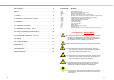
Main Menu
When in the main menu, if you continue to scroll down the LCD will display
options 3 & 4. When selected, option 3 will allow you reset the dB values to
factory default. (No Attenuation = Full Power).
Option 4 simply allows you to exit the main menu back to the home screen.
Click the ENTER button to access any selection.
Output Power
Another neat feature about the LCD Interface on this repeater is that in
addition to the current UL and DL gain values that scrolls on the home
screen, it also displays the active output power level of the unit. This can be
used as an indicator to determine how strong an input signal is being
received by the repeater. For example if the input signal is weak, the output
power will display “Output Power = Low”.
If your donor antenna is in the best location for receiving a good input signal
and the Output Power is still Low, then it could be that you either have a
compromised connector on your input coax cable, or that you need to add a
pre-amp to the system to boost the weak input signal.
3.3 Manual Gain Adjustment ~ UL / DL – Con’t.
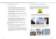
When do you adjust the Repeater Gain?
This repeater is equipped with an alarm feature that monitors the input gain.
If the input gain is too high, the Alarm LED will change color from green to
either, amber or red indicating the intensity or the error. High input gain can
occur if the donor antenna is in a location where the receive signal strength
(RSSI) from the cell tower is extremely good (-50dB or better) or if signal
oscillation is taking place. Signal Oscillation is when the amplified signal
from the indoor service antenna is being received back into the donor
antenna outside.
To determine what is the cause of your Alarm LED changing color you can
disconnect the indoor antenna / service line from the “INDOOR” port of the
repeater. If the LED does not change to green, then your input signal from
the cell tower is very strong and it is highly recommended you attenuate the
DL gain by 1dB increments till the LEDs turns green again. Then you must
match the same attenuation value to the UL, after which you can connect the
indoor antenna / service line again.
If after reconnecting the indoor antenna or service line, the LED changes
back to amber or red then signal oscillation is taking place. This is the result
of your indoor and outdoor antennas being too close to each other and
should therefore have more separation.
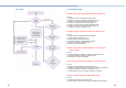
When complete, try making some test calls throughout the desired area of
coverage while monitoring the LEDs to see if it changes color. If you are
showing strong signal strength but your calls are not going through, it could
be that you need to attenuate your uplink gain a bit more. Keep in mind
however that you do not want to have more than a 5dB difference between
the uplink and downlink values for optimum system performance.
We encourage you to call us when commissioning your repeater system to
make sure you have seamless integration to the cellular network. We are
always happy to help. 1-866-4-JDTECK (53-8325).
A
void putting more than a 5dB difference between the Uplink and Downlink.
Down Navigation Button
13
14
Repeater not receiving a good input signal.