SECTION TABLE OF CONTENTS PAGE 1 INTRODUCTION . . . . . . . . . . . . . . . . . . . . . . . . . . . . . . . . . . . . . . . . . . . . . . . . . . . . . . . . . . . . . 3 1 2 THINGS TO KNOW BEFORE STARTING YOUR VEHICLE . . . . . . . . . . . . . . . . . . . . . . . . . . . . . 11 2 3 UNDERSTANDING THE FEATURES OF YOUR VEHICLE . . . . . . . . . . . . . . . . . . . . . . . . . . . . . . 71 3 4 UNDERSTANDING YOUR INSTRUMENT PANEL . . . . . . . . . . . . . . . . . . . . . . . . . . . . . . . . . . .
INTRODUCTION CONTENTS 䡵 Introduction . . . . . . . . . . . . . . . . . . . . . . . . . . . 4 䡵 Warnings And Cautions . . . . . . . . . . . . . . . . . . . 8 ▫ Roll Over Warning . . . . . . . . . . . . . . . . . . . . . 4 䡵 Vehicle Identification Number . . . . . . . . . . . . . . . 8 䡵 How To Use This Manual . . . . . . . . . . . . . . . . . . 6 䡵 Vehicle Modifications / Alterations . . . . . . . . . . .
INTRODUCTION INTRODUCTION Thank you for selecting a Jeep威 Commander and welcome to our worldwide family. This is a specialized utility vehicle designed for both on-road and off-road use. It can go places and perform tasks for which conventional two-wheel drive vehicles were not intended. However, on-road ride and handling will have a different feel from what drivers experience with other vehicles, so take time to become familiar with your vehicle.
INTRODUCTION 5 Do not attempt sharp turns or abrupt maneuvers or other unsafe driving actions that can cause loss of vehicle control. Failure to operate this vehicle safely may result in an accident, roll over of the vehicle, and severe or fatal injury. Drive carefully. Failure to use driver and passenger seat belts provided is a major cause of severe or fatal injury. In fact, the U.S.
INTRODUCTION NOTE: After you read the manual, it should be stored in the vehicle for convenient reference and remain with the vehicle when sold so that the new owner will be aware of all safety warnings. When it comes to service, remember that your authorized dealer knows your vehicle best, has the factory-trained technicians and genuine Mopar威 parts, and is interested in your satisfaction.
INTRODUCTION 7 1
INTRODUCTION WARNINGS AND CAUTIONS This manual contains WARNINGS against operating procedures which could result in an accident or bodily injury. It also contains CAUTIONS against procedures which could result in damage to your vehicle. If you do not read this entire manual you may miss important information. Observe all Warnings and Cautions.
INTRODUCTION 9 VEHICLE MODIFICATIONS / ALTERATIONS 1 WARNING! Any modifications or alterations to this vehicle could seriously affect its roadworthiness and safety and may lead to an accident resulting in serious injury or death.
THINGS TO KNOW BEFORE STARTING YOUR VEHICLE 2 CONTENTS 䡵 A Word About Your Keys . . . . . . . . . . . . . . . . . .14 ▫ To Set The Alarm . . . . . . . . . . . . . . . . . . . . . .18 ▫ Ignition Key Removal . . . . . . . . . . . . . . . . . . .14 ▫ To Disarm The System . . . . . . . . . . . . . . . . . . .19 ▫ Key-In-Ignition Reminder . . . . . . . . . . . . . . . .15 䡵 Illuminated Entry . . . . . . . . . . . . . . . . . . . . . . . .19 䡵 Sentry Key Immobilizer System . . . . . . . . . . . . . .
THINGS TO KNOW BEFORE STARTING YOUR VEHICLE ▫ Transmitter Battery Service . . . . . . . . . . . . . . .24 ▫ Lap/Shoulder Belts . . . . . . . . . . . . . . . . . . . . .38 䡵 Remote Starting System — If Equipped . . . . . . . .25 ▫ Lap/Shoulder Belt Operating Instructions . . . . .39 䡵 Door Locks . . . . . . . . . . . . . . . . . . . . . . . . . . . .26 ▫ Adjustable Upper Shoulder Belt Anchorage . . . .42 ▫ Manual Door Locks . . . . . . . . . . . . . . . . . . . . .
THINGS TO KNOW BEFORE STARTING YOUR VEHICLE 13 ▫ Exhaust Gas . . . . . . . . . . . . . . . . . . . . . . . . . .68 ▫ Safety Checks You Should Make Inside The Vehicle . . . . . . . . . . . . . . . . . . . . . . . . . . . . . .69 ▫ Safety Checks You Should Make Outside The Vehicle . . . . . . . . . . . . . . . . . . . . . . . . . . . . . .
THINGS TO KNOW BEFORE STARTING YOUR VEHICLE A WORD ABOUT YOUR KEYS The keys for your new vehicle are enclosed in a plastic bag with the key code number on it. If you received your keys without the bag, ask your authorized dealer to give you the number. The key code can also be obtained by your authorized dealer from your vehicle invoice. Ignition Key Removal Place the shift lever in P (Park). Turn the ignition switch to the OFF position, and remove the key.
THINGS TO KNOW BEFORE STARTING YOUR VEHICLE 15 WARNING! Leaving children in a vehicle unattended is dangerous for a number of reasons. A child or others could be injured. Children should be warned not to touch the parking brake, brake pedal or the gear selector lever. Don’t leave the keys in the ignition. A child could operate power windows, other controls, or move the vehicle. CAUTION! An unlocked car is an invitation to thieves.
THINGS TO KNOW BEFORE STARTING YOUR VEHICLE light will come on for 3 seconds immediately after the ignition switch is turned on for a bulb check. Afterwards, if the bulb remains on, this indicates a malfunction in the electronics. If the bulb begins to flash immediately after the ignition switch is turned on, this indicates that an invalid key is being used to start the vehicle. Both of these conditions will result in the engine being shut down after 2 seconds of running.
THINGS TO KNOW BEFORE STARTING YOUR VEHICLE 17 Replacement Keys Customer Key Programming NOTE: Only keys that have been programmed to the vehicle electronics can be used to start the vehicle. Once a Sentry Key has been programmed to a vehicle, it cannot be programmed to any other vehicle. You can program new keys to the system if you have two valid keys by doing the following: At the time of purchase, the original owner is provided with a four digit PIN number.
THINGS TO KNOW BEFORE STARTING YOUR VEHICLE 4. Insert a blank Sentry Key into the ignition switch and turn the ignition switch ON within 60 seconds. After 10 seconds, a single chime will sound. The SKIM indicator light will stop flashing, turn on for 3 seconds; then turn off. The new Sentry Key has been programmed. Repeat this process to program up to a total of 8 keys. General Information The Sentry Key Immobilizer System complies with FCC rules part 15 and with RSS-210 of Industry Canada.
THINGS TO KNOW BEFORE STARTING YOUR VEHICLE 19 the door lock plunger located on the inside of the doors or with the driver’s door key lock cylinder, will not set the alarm. the system. The Security Alarm System will not disarm with a manual unlock, either through the lock plunger located on the inside of the door, or through a key in the driver’s door key cylinder. To Disarm the System To disarm the system, use the remote keyless entry transmitter.
THINGS TO KNOW BEFORE STARTING YOUR VEHICLE NOTE: If the key is in the ignition switch, then all buttons on that transmitter will be disabled. The buttons on the remaining transmitters will work. If the vehicle is shifted out of P (Park), all the transmitter buttons are disabled for all keys.
THINGS TO KNOW BEFORE STARTING YOUR VEHICLE 21 NOTE: If desired, the system can be programmed to unlock all doors on the first press of the “Unlock” button. Refer to “Remote Unlock Driver’s Door 1st” in the Personal Settings section of the “Electronic Vehicle Information Center (EVIC)”, or simply follow these steps: 1. Press and hold the “Lock” button for 4 to 10 seconds. 2. While the “Lock” button is pressed, (after 4 seconds) press the “Unlock” button. Release both buttons.
THINGS TO KNOW BEFORE STARTING YOUR VEHICLE Customer Programmable Features of the “Electronic Vehicle Information Center (EVIC)” section or by following these steps. 1. Press and hold the “Lock” button for 4 to 10 seconds. 2. While the “Lock” button is pressed (after 4 seconds), press the PANIC button. Release both buttons. The “Sound Horn On Lock” feature can be reactivated by repeating this procedure.
THINGS TO KNOW BEFORE STARTING YOUR VEHICLE 23 NOTE: The interior lights will turn off when the ignition is switched to the ACC or ON position after the panic alarm is activated. However, the exterior lights and horn will remain on. NOTE: When you turn off the panic alarm by pressing the PANIC button a second time, you may have to be closer to the vehicle due to the radio frequency noises of the system.
THINGS TO KNOW BEFORE STARTING YOUR VEHICLE Transmitter Battery Service The recommended replacement battery is one CR2032 battery. NOTE: Do not touch the battery terminals that are on the back housing or the printed circuit board. 1. With the transmitter buttons facing down, remove the small screw, and separate the two halves of the transmitter. Make sure not to damage the rubber gasket during removal. Separating Transmitter Halves 2. Remove and replace the battery.
THINGS TO KNOW BEFORE STARTING YOUR VEHICLE 25 3. To reassemble the transmitter case, join the two halves of the case together. Install and tighten the screw until snug. Make sure there is an even “gap” between the two halves. Test transmitter operation.
THINGS TO KNOW BEFORE STARTING YOUR VEHICLE unlocked, you have 60 seconds to enter the vehicle, insert the key into the ignition, and move it to the RUN position. Otherwise, the engine will cancel remote start and automatically turn off. Remote start will also cancel if any of the following occur: • If the engine stalls or RPM exceeds 2500 • Any engine warning lamps come on • The hood is opened • The hazard switch is pressed • The transmission is moved out of P (Park).
THINGS TO KNOW BEFORE STARTING YOUR VEHICLE 27 Power Door Locks — If Equipped A door lock switch is on each front door panel. Press this switch to lock or unlock the doors. If you press the door lock switch while the keys are in the ignition switch, and the driver’s door is open, the doors will not lock. The rear doors cannot be opened from inside the vehicle until you pull up the lock plungers.
THINGS TO KNOW BEFORE STARTING YOUR VEHICLE Automatic Unlock on Exit Feature — Only Available if Auto Lock is Enabled This feature will unlock all the doors when the driver’s door is opened if the vehicle is stopped and in P (Park) or N (Neutral). Refer to “Electronic Vehicle Information Center (EVIC) — Customer Programmable Features” in Section 4 of this manual or see your authorized dealer. WARNING! Avoid trapping anyone in the vehicle in a collision.
THINGS TO KNOW BEFORE STARTING YOUR VEHICLE 29 WINDOWS Power Windows The power window controls are located on the driver’s door trim panel. There is a single switch on the front passenger door/rear doors which operates the front passenger/rear passenger door windows. The window controls will operate only when the ignition switch is in the ON or ACCESSORY position. 2 Power Window Switches The power window switches remain active for up to 10 minutes after the ignition switch has been turned off.
THINGS TO KNOW BEFORE STARTING YOUR VEHICLE Auto Down Both the driver and front passenger window switch has an “Auto Down” feature. Press the window switch past the first detent, release, and the window will go down automatically. To cancel the “Auto Down” movement, operate the switch in either the up or down direction and release the switch. To stop the window from going all the way down during the auto-down operation, pull up on the switch briefly.
THINGS TO KNOW BEFORE STARTING YOUR VEHICLE 31 WARNING! There is no anti-pinch protection when the window is almost closed. Be sure to clear all objects from the window before closing. 2 Resetting the Auto-Up Feature Should the Auto-Up feature stop working the window probably needs to be reset. To reset Auto-Up: Pull the window switch up and close the window completely, then pull and hold the switch for 1 second.
THINGS TO KNOW BEFORE STARTING YOUR VEHICLE Wind Buffeting Wind buffeting can be described as the perception of pressure on the ears or a helicopter type sound in the ears. Your vehicle may exhibit wind buffeting with the windows down, or the sunroof (if equipped) in certain open or partially open positions. This is a normal occurrence and can be minimized. If the buffeting occurs with the sunroof open, adjust the sunroof opening to minimize the buffeting.
THINGS TO KNOW BEFORE STARTING YOUR VEHICLE 33 WARNING! Driving with the liftgate open can allow poisonous exhaust gases into your vehicle. You and your passengers could be injured by these fumes. Keep the liftgate closed when you are operating the vehicle. 2 Liftgate Flipper Glass The liftgate flipper glass is also unlocked when the liftgate is unlocked. To open the flipper glass, push up on the window switch located on the liftgate.
THINGS TO KNOW BEFORE STARTING YOUR VEHICLE Once the liftgate flipper glass has been opened, connection to the rear window wiper is interrupted, preventing activation of the rear wiper blade while the flipper glass is open. liftgate is fully open, pressing the button twice within five seconds a second time will close the liftgate. WARNING! Driving with the flipper glass open can allow poisonous exhaust gases into your vehicle. You and your passengers could be injured by these fumes.
THINGS TO KNOW BEFORE STARTING YOUR VEHICLE 35 NOTE: • In the event of a power malfunction to the liftgate, an emergency liftgate latch release can be used to open the liftgate. The emergency liftgate latch release can be accessed through a snap-in cover located on the liftgate trim panel. WARNING! During power operation, personal injury or cargo damage may occur. Ensure the liftgate travel path is clear. Make sure the liftgate is closed and latched before driving away.
THINGS TO KNOW BEFORE STARTING YOUR VEHICLE • The power liftgate buttons will not operate if the vehicle is in gear or the vehicle speed is above 0 mph (0 km/h). • The power liftgate will not operate in temperatures below ⫺22° F (⫺30° C) or temperatures above 150° F (65° C). Be sure to remove any buildup of snow or ice from the liftgate before pressing any of the power liftgate switches.
THINGS TO KNOW BEFORE STARTING YOUR VEHICLE 37 OCCUPANT RESTRAINTS Some of the most important safety features in your vehicle are the restraint systems. These include the front and rear seat belts for the driver and all passengers, front airbags for both the driver and right front passenger, and, window bags for the driver and passengers seated next to a window. If you will be carrying children too small for adult-size belts, your seat belts also can be used to hold infant and child restraint systems.
THINGS TO KNOW BEFORE STARTING YOUR VEHICLE Research has shown that seat belts save lives, and they can reduce the seriousness of injuries in a collision. Some of the worst injuries happen when people are thrown from the vehicle. Seat belts reduce the possibility of ejection and the risk of injury caused by striking the inside of the vehicle. Everyone in a motor vehicle should be belted at all times to reduce or prevent injuries.
THINGS TO KNOW BEFORE STARTING YOUR VEHICLE 39 Lap/Shoulder Belt Operating Instructions 1. Enter the vehicle and close the door. Sit back and adjust the seat. 2 2. The seat belt latch plate is above the back of your seat. Grasp the latch plate and pull out the belt. Slide the latch plate up the webbing as far as necessary to make the belt go around your lap.
THINGS TO KNOW BEFORE STARTING YOUR VEHICLE 3. When the belt is long enough to fit, insert the latch plate into the buckle until you hear a “click.” Latch Plate To Buckle WARNING! A belt that is buckled into the wrong buckle will not protect you properly. The lap portion could ride too high on your body, possibly causing internal injuries. Always buckle your belt into the buckle nearest you. A belt that is too loose will not protect you as well.
THINGS TO KNOW BEFORE STARTING YOUR VEHICLE 41 4. Position the lap belt across your thighs, below your abdomen. To remove slack in the lap portion, pull up a bit on the shoulder belt. To loosen the lap belt if it is too tight, tilt the latch plate and pull on the lap belt. A snug belt reduces the risk of sliding under the belt in a collision. 5. Position the shoulder belt on your chest so that it is comfortable and not resting on your neck. The retractor will withdraw any slack in the belt.
THINGS TO KNOW BEFORE STARTING YOUR VEHICLE 6. To release the belt, push the red button marked PRESS on the buckle. The belt will automatically retract to its stowed position. If necessary, slide the latch plate down the webbing to allow it to retract fully. WARNING! Adjustable Upper Shoulder Belt Anchorage In the front seating positions, the shoulder belt can be adjusted upward or downward to position the belt away from your neck.
THINGS TO KNOW BEFORE STARTING YOUR VEHICLE 43 As a guide, if you are shorter than average, you will prefer a lower position, and if you are taller than average, you’ll prefer a higher position. When you release the anchorage, try to move it up or down to make sure that it is locked in position. Automatic Locking Mode — If Equipped In this mode, the shoulder belt is automatically prelocked. The belt will still retract to remove any slack in the shoulder belt.
THINGS TO KNOW BEFORE STARTING YOUR VEHICLE This safety belt system has a retractor assembly that is designed to release webbing in a controlled manner. This feature is designed to help reduce the belt force acting on the occupant’s chest. WARNING! • The belt and retractor assembly must be replaced if the seat belt assembly “automatic locking retractor” feature or any other seat belt function is not working properly when checked according to the procedures in the Service Manual.
THINGS TO KNOW BEFORE STARTING YOUR VEHICLE 45 Seat Belts and Pregnant Women We recommend that pregnant women use the seat belts throughout their pregnancy. Keeping the mother safe is the best way to keep the baby safe. Pregnant women should wear the lap part of the belt across the thighs and as snug across the hips as possible. Keep the belt low so that it does not come across the abdomen. That way the strong bones of the hips will take the force if there is a collision.
THINGS TO KNOW BEFORE STARTING YOUR VEHICLE Driver And Front Passenger Supplemental Restraint Systems (SRS) This vehicle has airbags for both the driver and right front passenger as a supplement to the seat belt restraint systems. The driver’s front airbag is mounted in the steering wheel. The passenger side airbag is mounted in the instrument panel, above the glove compartment. The words SRS/AIRBAG are embossed on the airbag covers.
THINGS TO KNOW BEFORE STARTING YOUR VEHICLE 47 This vehicle is equipped with window bags to protect the driver, front, and rear passengers sitting next to a window. They are located above the side windows. Their covers are also labeled SRS/AIRBAG. Window Airbag Location NOTE: Airbag covers may not be obvious in the interior trim; but they will open to allow airbag deployment. WARNING! • Do not put anything on or around the front airbag covers or attempt to manually open them.
THINGS TO KNOW BEFORE STARTING YOUR VEHICLE NOTE: Do not use a clothing bar mounted to the coat hooks in this vehicle. A clothing bar will impede the proper performance of the window bags. The front airbags have a multi stage inflator design. This allows the airbag to have different rates of inflation that are based on collision severity. Along with the seat belts, front airbags work with the instrument panel knee bolsters to provide improved protection for the driver and front passenger.
THINGS TO KNOW BEFORE STARTING YOUR VEHICLE 49 Children that are not big enough to properly wear the vehicle seat belt should be secured in the rear seat, in a child restraint or belt-positioning booster seat. Older children who do not use child restraints or beltpositioning booster seats should ride properly buckled up in the rear seat. Never allow children to slide the shoulder belt behind them or under their arm.
THINGS TO KNOW BEFORE STARTING YOUR VEHICLE WARNING! • Relying on the airbags alone could lead to more severe injuries in a collision. The airbags work with your seat belt to restrain you properly. In some collisions the airbags won’t deploy at all. Always wear your seat belts even though you have airbags. • Being too close to the steering wheel or instrument panel during airbag deployment could cause serious injury. Airbags need room to inflate.
THINGS TO KNOW BEFORE STARTING YOUR VEHICLE 51 How The Airbag System Works • The Occupant Restraint Control (ORC) Module determines if a frontal, side, or rollover collision is severe enough to require the front and/or side airbags to inflate. The front airbag inflators are designed to provide different rates of airbag inflation from direction provided by the ORC. The ORC will detect roll overs, not rear impacts.
THINGS TO KNOW BEFORE STARTING YOUR VEHICLE • The Driver and Passenger Airbag/Inflator Units are located in the center of the steering wheel and the right side of the instrument panel. When the ORC detects a collision requiring the airbags, it signals the inflator units. A large quantity of nontoxic gas is generated to inflate the front airbags. Different airbag inflation rates are possible, based on collision severity and occupant size.
THINGS TO KNOW BEFORE STARTING YOUR VEHICLE 53 If A Deployment Occurs The airbag system is designed to deploy when the Occupant Restraint Control (ORC) Module detects a moderate-to-severe frontal collision, to help restrain the driver and front passenger, and then to immediately deflate. NOTE: A frontal collision that is not severe enough to need airbag protection will not activate the system. This does not mean something is wrong with the airbag system.
THINGS TO KNOW BEFORE STARTING YOUR VEHICLE WARNING! Deployed airbags and seat belt pretensioners cannot protect you in another collision. Have the airbags, seat belt pretensioners, and seat belt retractor assembly, replaced by an authorized dealer as soon as possible. Enhanced Accident Response Feature If the airbags deploy after an impact and the electrical system remains functional, vehicles equipped with power door locks will unlock automatically.
THINGS TO KNOW BEFORE STARTING YOUR VEHICLE 55 Airbag Warning Light You will want to have the airbag system ready to inflate for your protection in an impact. The airbag system is designed to be maintenance free. If any of the following occurs, have an authorized dealer service the system promptly: • Does not come on during the 6 to 8 seconds after the ignition switch is first turned on. • Remains on after the 6 to 8 second interval. • Comes on for any period of time while driving.
THINGS TO KNOW BEFORE STARTING YOUR VEHICLE provided to the custodial entity upon request. General data that does not identify particular vehicles or crashes may be released for incorporation in aggregate crash databases, such as those maintained by the US government and various states. Data of a potentially sensitive nature, such as would identify a particular driver, vehicle, or crash, will be treated confidentially.
THINGS TO KNOW BEFORE STARTING YOUR VEHICLE 57 Child Restraint Everyone in your vehicle needs to be buckled up all the time — babies and children, too. Every state in the United States and all Canadian provinces require that small children ride in proper restraint systems. This is the law, and you can be prosecuted for ignoring it. Children 12 years and under should ride properly buckled up in a rear seat, if available.
THINGS TO KNOW BEFORE STARTING YOUR VEHICLE • The infant carrier is only used rearward-facing in the vehicle. It is recommended for children who weigh up to about 20 lbs (9 kg). “Convertible” child seats often have a higher weight limit in the rearward-facing direction than infant carriers do, so they can be used rearward-facing by children who weigh more than 20 lbs (9 kg) but are less than one year old.
THINGS TO KNOW BEFORE STARTING YOUR VEHICLE 59 Standards. The manufacturer also recommends that you try a child restraint in the vehicle seats where you will use it before you buy it. • The restraint must be appropriate for your child’s weight and height. Check the label on the restraint for weight and height limits. • Carefully follow the instructions that come with the restraint. If you install the restraint improperly, it may not work when you need it.
THINGS TO KNOW BEFORE STARTING YOUR VEHICLE • If the belt still cannot be tightened, or if pulling and pushing on the restraint loosens the belt, disconnect the latch plate from the buckle, turn the buckle around, and insert the latch plate into the buckle again. If you still cannot make the child restraint secure, try a different seating position. • Buckle the child into the restraint exactly as the manufacturer’s instructions tell you.
THINGS TO KNOW BEFORE STARTING YOUR VEHICLE 61 Children Too Large for Booster Seats Children who are large enough to wear the shoulder belt comfortably, and whose legs are long enough to bend over the front of the seat when their back is against the seat back, should use the lap/shoulder belt in a rear seat. • Make sure that the child is upright in the seat. • The lap portion should be low on the hips and as snug as possible. • Check belt fit periodically.
THINGS TO KNOW BEFORE STARTING YOUR VEHICLE kits or retro-fit kits. You are urged to take advantage of all the available attachments provided with your child restraint in any vehicle. NOTE: When using the LATCH attaching system to install a child restraint, please ensure that all seat belts not being used for occupant restraints are stowed and out of reach of children.
THINGS TO KNOW BEFORE STARTING YOUR VEHICLE 63 Installing the LATCH-Compatible Child Restraint System We urge that you carefully follow the directions of the manufacturer when installing your child restraint. Not all child restraint systems will be installed as described here. Again, carefully follow the installation instructions that were provided with the child restraint system.
THINGS TO KNOW BEFORE STARTING YOUR VEHICLE In addition, there are tether strap anchorages behind each rear outboard seating position located on the back of the seat. Tether Strap Mounting Many, but not all restraint systems will be equipped with separate straps on each side, with each having a hook or connector for attachment to the lower anchorage and a means of adjusting the tension in the strap.
THINGS TO KNOW BEFORE STARTING YOUR VEHICLE 65 WARNING! Improper installation of a child restraint to the LATCH anchorages can lead to failure of an infant or child restraint. The child could be badly injured or killed. Follow the manufacturer’s directions exactly when installing an infant or child restraint.
THINGS TO KNOW BEFORE STARTING YOUR VEHICLE to do something more. Disconnect the latch plate from the buckle, turn the buckle around, and insert the latch plate into the buckle again. If you still can’t make the child restraint secure, try a different seating position. To attach a child restraint tether strap: Route the tether strap over the seat back and attach the hook to the tether anchor located on the back of the seat.
THINGS TO KNOW BEFORE STARTING YOUR VEHICLE 67 Transporting Pets Airbags deploying in the front seat could harm your pet. An unrestrained pet will be thrown about and possibly injured, or injure a passenger during panic braking or in a collision. Pets should be restrained in the rear seat in pet harnesses or pet carriers that are secured by seat belts. ENGINE BREAK-IN RECOMMENDATIONS A long break-in period is not required for the engine in your new vehicle.
THINGS TO KNOW BEFORE STARTING YOUR VEHICLE stopped in an open area with engine running for more than a short period, adjust the ventilation system to force fresh, outside air into the vehicle. SAFETY TIPS Exhaust Gas WARNING! Exhaust gases can injure or kill. They contain carbon monoxide (CO) which is colorless and odorless. Breathing it can make you unconscious and can eventually poison you. To avoid breathing (CO) follow the safety tips below. • Do not inhale exhaust gases.
THINGS TO KNOW BEFORE STARTING YOUR VEHICLE 69 Safety Checks You Should Make Inside The Vehicle Seat Belts Inspect the belt system periodically, checking for cuts, frays and loose parts. Damaged parts must be replaced immediately. Do not disassemble or modify the system. Seat belt assemblies must be replaced after an accident if they have been damaged (bent retractor, torn webbing, etc.). If there is any question regarding belt or retractor condition, replace the belt.
THINGS TO KNOW BEFORE STARTING YOUR VEHICLE Safety Checks You Should Make Outside The Vehicle Tires Examine tires for excessive tread wear or uneven wear patterns. Check for stones, nails, glass, or other objects lodged in the tread. Inspect for tread cuts or sidewall cracks. Check wheel nuts for tightness and tires (including spare) for proper pressure. Lights Have someone observe the operation of all exterior lights while you work the controls.
UNDERSTANDING THE FEATURES OF YOUR VEHICLE CONTENTS 䡵 Mirrors . . . . . . . . . . . . . . . . . . . . . . . . . . . . . . .76 ▫ Inside Day/Night Mirror . . . . . . . . . . . . . . . . .76 ▫ Automatic Dimming Mirror — If Equipped . . . .77 ▫ Outside Mirrors . . . . . . . . . . . . . . . . . . . . . . .77 ▫ Exterior Mirrors Folding Feature . . . . . . . . . . .78 ▫ Driver’s Outside Automatic Dimming Mirror — If Equipped . . . . . . . . . . . . . . . . . . . . . . . . . .
UNDERSTANDING THE FEATURES OF YOUR VEHICLE ▫ Things You Should Know About Your UConnect™ System . . . . . . . . . . . . . . . . . . . . .97 ▫ Setting Memory Positions And Linking Remote Keyless Entry Transmitter To Memory . . . . . . . 114 䡵 Seats . . . . . . . . . . . . . . . . . . . . . . . . . . . . . . . . 103 ▫ Memory Position Recall . . . . . . . . . . . . . . . . . 115 ▫ Front Manual Seat Adjustment . . . . . . . . . . . . 103 ▫ To Disable A Transmitter Linked To Memory . .
UNDERSTANDING THE FEATURES OF YOUR VEHICLE 73 ▫ Daytime Running Lights — If Equipped . . . . . 123 䡵 Tilt Steering Column . . . . . . . . . . . . . . . . . . . . 130 ▫ Lights-On Reminder . . . . . . . . . . . . . . . . . . . 123 䡵 Adjustable Pedals — If Equipped . . . . . . . . . . . 130 ▫ Fog Lights — If Equipped . . . . . . . . . . . . . . . 123 䡵 Electronic Speed Control . . . . . . . . . . . . . . . . . . 132 ▫ Turn Signals . . . . . . . . . . . . . . . . . . . . . . . . . 124 ▫ To Activate . .
UNDERSTANDING THE FEATURES OF YOUR VEHICLE ▫ BAS (Brake Assist System) . . . . . . . . . . . . . . . 136 ▫ Turning The Rear Camera Off . . . . . . . . . . . . 150 ▫ ERM (Electronic Roll Mitigation) . . . . . . . . . . 137 䡵 Overhead Console — If Equipped . . . . . . . . . . . 151 ▫ ESP (Electronic Stability Program) . . . . . . . . . 138 䡵 Garage Door Opener — If Equipped . . . . . . . . . 151 ▫ ESP/BAS Warning Lamp And ESP/TCS Indicator Light . . . . . . . . . . . . . . . . . . . . . . .
UNDERSTANDING THE FEATURES OF YOUR VEHICLE 75 ▫ Pinch Protect Override . . . . . . . . . . . . . . . . . 160 䡵 Power Outlet . . . . . . . . . . . . . . . . . . . . . . . . . . 162 ▫ Venting Sunroof - Express . . . . . . . . . . . . . . . 160 䡵 Cup Holders . . . . . . . . . . . . . . . . . . . . . . . . . . 163 ▫ Sunshade Operation . . . . . . . . . . . . . . . . . . . 160 䡵 Cargo Area Features . . . . . . . . . . . . . . . . . . . . . 165 ▫ Wind Buffeting . . . . . . . . . . . . . . . . . . . . . . .
UNDERSTANDING THE FEATURES OF YOUR VEHICLE MIRRORS Inside Day/Night Mirror The mirror should be adjusted to center on the view through the rear window. Adjusting Rear View Mirror A two-point pivot system allows for horizontal and vertical adjustment of the mirror. Annoying headlight glare from vehicles behind you can be reduced by moving the small control under the mirror to the night position (toward rear of vehicle). The mirror should be adjusted while set in the day position (toward windshield).
UNDERSTANDING THE FEATURES OF YOUR VEHICLE 77 Automatic Dimming Mirror — If Equipped This mirror automatically adjusts for annoying headlight glare from vehicles behind you. You can turn the feature on or off by pressing the button at the base of the mirror. A light next to the button will indicate when the dimming feature is activated. CAUTION! To avoid damage to the mirror during cleaning, never spray any cleaning solution directly onto the mirror.
UNDERSTANDING THE FEATURES OF YOUR VEHICLE WARNING! Vehicles and other objects seen in the passenger side convex mirror will look smaller and farther away than they really are. Relying too much on your passenger side convex mirror could cause you to collide with another vehicle or other object. Use your inside mirror when judging the size or distance of a vehicle seen in the passenger side convex mirror. Some vehicles will not have a convex passenger side mirror.
UNDERSTANDING THE FEATURES OF YOUR VEHICLE 79 After selecting a mirror move the knob in the same direction you want the mirror to move. Use the center off position to guard against accidentally moving a mirror position. Power mirror preselected positions can be controlled by the optional Memory Seat Feature. Refer to “Driver Memory Seat” in this section for details. Heated Remote Control Mirrors — If Equipped These mirrors are heated to melt frost or ice.
UNDERSTANDING THE FEATURES OF YOUR VEHICLE Lift the cover to reveal the mirror. The light will turn on automatically. Lighted Vanity Mirror Sun Visor Extension (If Equipped) This feature has a pull out extension on the sun visor for increased coverage. HANDS–FREE COMMUNICATION (UConnect™) — IF EQUIPPED UConnect™ is a voice-activated, hands-free, in- vehicle communications system. UConnect™ allows you to dial a phone number with your cellular phone using simple voice commands (e.g.
UNDERSTANDING THE FEATURES OF YOUR VEHICLE 81 The UConnect™ phonebook enables you to store up to 32 names and four numbers per name. Each language has a separate 32-name phonebook accessible only in that language. This system is driven through your Bluetooth™ Hands-Free profile cellular phone.
UNDERSTANDING THE FEATURES OF YOUR VEHICLE Headset Profile), you may not be able to use any UConnect™ features. Refer to your cellular service provider or the phone manufacturer for details. • Prior to giving a voice command, one must wait for the voice on beep, which follows the ⬙Ready⬙ prompt or another prompt. The UConnect™ system is fully integrated with the vehicle’s audio system.
UNDERSTANDING THE FEATURES OF YOUR VEHICLE 83 Voice Command Tree Refer to “Voice Tree” at the end of this section. Help Command If you need assistance at any prompt, or if you want to know your options are at any prompt, say ⬙Help⬙ following the voice on beep. The UConnect™ system will play all the options at any prompt if you ask for help. To activate the UConnect™ system from idle, simply press the ’Phone’ button and follow audible prompts for directions.
UNDERSTANDING THE FEATURES OF YOUR VEHICLE The following are general phone to UConnect™ System pairing instructions: • Press the ’Phone’ button to begin. • After the ⬙Ready⬙ prompt and the following beep, say ⬙Setup Phone Pairing⬙ and follow the audible prompts. • When prompted, after the voice on beep, say ⬙Pair a Phone⬙ and follow the audible prompts. • You will be asked to say a four-digit pin number, which you will later need to enter into your cellular. You can enter any four-digit pin number.
UNDERSTANDING THE FEATURES OF YOUR VEHICLE 85 • System will prompt you to say the number you want call. • For example, you can say ⬙234-567-8901.⬙ • The UConnect™ system will confirm the phone number and then dial. The number will appear in the display of certain radios. you can say ⬙John Doe,⬙ where John Doe is a previously stored name entry in the UConnect™ phonebook. Refer to ⬙Add Names to Your UConnect™ Phonebook,⬙ to learn how to store a name in the phonebook.
UNDERSTANDING THE FEATURES OF YOUR VEHICLE • When prompted, say the name of the new entry. Use of long names helps the voice recognition and is recommended. For example, say ⬙Robert Smith⬙ or ⬙Robert⬙ instead of ⬙Bob.⬙ • When prompted, enter the number designation (e.g., ⬙Home,⬙ ⬙Work,⬙ ⬙Mobile,⬙ or ⬙Pager⬙). This will allow you to store multiple numbers for each phonebook entry, if desired. four associated phone numbers and designations.
UNDERSTANDING THE FEATURES OF YOUR VEHICLE 87 After you are finished editing an entry in the phonebook, you will be given the opportunities to edit another entry in the phonebook, call the number you just edited, or return to the main menu. ⬙Phonebook Edit⬙ can be used to add another phone number to a name entry that already exists in the phonebook. For example, the entry John Doe may have a mobile and a home number, but you can add John Doe’s work number later using the ⬙Phonebook Edit⬙ feature.
UNDERSTANDING THE FEATURES OF YOUR VEHICLE Delete All Entries in the UConnect™ Phonebook • Press the ’Phone’ button to begin. • After the ⬙Ready⬙ prompt and the following beep, say ⬙Phonebook Erase All.⬙ • The UConnect™ system will ask you to verify that you wish to delete all the entries from the phonebook. • After confirmation, the phonebook entries will be deleted. List All Names in the UConnect™ Phonebook • Press the ’Phone’ button to begin.
UNDERSTANDING THE FEATURES OF YOUR VEHICLE 89 Answer or Reject an Incoming Call - No Call Currently in Progress When you receive a call on your cellular phone, the UConnect™ system will interrupt the vehicle audio system, if on, and will ask if you would like to answer the call. To reject the call, press and hold the ’Phone’ button until you hear a single beep indicating that the incoming call was rejected.
UNDERSTANDING THE FEATURES OF YOUR VEHICLE Toggling Between Calls If two calls are in progress (one active and one on hold), press the ’Phone’ button until you hear a single beep indicating that the active and hold status of the two calls have switched. Only one call can be placed on hold at one time.
UNDERSTANDING THE FEATURES OF YOUR VEHICLE 91 Call Continuation Call continuation is progression of a phone call on UConnect™ system after the vehicle ignition key has been switched to off.
UNDERSTANDING THE FEATURES OF YOUR VEHICLE Emergency Assistance If you are in an emergency and the mobile phone is reachable: The UConnect™ system does slightly lower your chances of successfully making a phone call as to that for the cell phone directly. • Pick up the phone and manually dial the emergency number for your area.
UNDERSTANDING THE FEATURES OF YOUR VEHICLE 93 Please refer to the 24-Hour “Towing Assistance” coverage details in the Warranty information booklet and on the 24–Hour Towing Assistance Card. Paging To learn how to page, refer to ⬙Working with Automated Systems.⬙ Paging works properly except for pagers of certain companies which time-out a little too soon to work properly with the UConnect™ system. Voice Mail Calling To learn how to access your voice mail, refer to ⬙Working with Automated Systems.
UNDERSTANDING THE FEATURES OF YOUR VEHICLE Barge In - Overriding Prompts The ’Voice Recognition’ button can be used when you wish to skip part of a prompt and issue your voice recognition command immediately. For example, if a prompt is playing ⬙Would you like to pair a phone, clear aѧ,⬙ you could press the ’Voice Recognition’ button and say ⬙Pair a Phone⬙ to select that option without having to listen to the rest of the voice prompt.
UNDERSTANDING THE FEATURES OF YOUR VEHICLE 95 NOTE: Certain brands of mobile phones do not send the dial ring to the UConnect™ system to play it on the vehicle audio system, so you will not hear it. Under this situation, after successfully dialing a number, the user may feel that the call did not go through even though the call is in progress. Once your call is answered, you will hear the audio.
UNDERSTANDING THE FEATURES OF YOUR VEHICLE Connect or Disconnect Link Between the UConnect™ System and Cellular Phone Your cellular phone can be paired with many different electronic devices, but can only be actively ⬙connected⬙ with one electronic device at a time. If you would like to connect or disconnect the Bluetooth™ connection between a UConnect™ paired cellular phone and the UConnect™ system, then follow the instruction described in your cellular phone user’s manual.
UNDERSTANDING THE FEATURES OF YOUR VEHICLE 97 • You can also press the ⬘Voice Recognition’ button anytime while the list is being played, and then choose the phone that you wish to select. • You can also press the ⬘Voice Recognition’ button anytime while the list is being played and then choose the phone you wish to delete. • The selected phone will be used for the next phone call.
UNDERSTANDING THE FEATURES OF YOUR VEHICLE • Performance is maximized under: • low-to-medium blower setting, • low-to-medium vehicle speed, • low road noise, • smooth road surface, • fully closed windows, • dry weather condition. • Even though the system is designed for users speaking in North American English, French, and Spanish accents, the system may not always work for some.
UNDERSTANDING THE FEATURES OF YOUR VEHICLE 99 • smooth road surface, • fully closed windows, and • dry weather condition. • Operation from driver seat. • Performance, such as audio clarity, echo, and loudness to a large degree rely on the phone and network, and not the UConnect™ system. • Echo at far end can sometime be reduced by lowering the in-vehicle audio volume. Bluetooth Communication Link Occasionally, Cellular phones have been found to lose connection to the UConnect™ system.
UNDERSTANDING THE FEATURES OF YOUR VEHICLE
UNDERSTANDING THE FEATURES OF YOUR VEHICLE 101 3
UNDERSTANDING THE FEATURES OF YOUR VEHICLE
UNDERSTANDING THE FEATURES OF YOUR VEHICLE 103 North American English Primary Alternate(s) Zero Oh Add location Add new All All of them Confirmation prompts Confirmations prompts Delete a name Delete Language Select language List names List all List paired phones List phones Pager Beeper Phone pairing Pairing Phonebook Phone book Return to main menu Return.
UNDERSTANDING THE FEATURES OF YOUR VEHICLE Front Seat Adjustment — Recline To adjust the seatback, lift the lever located on the outboard side of the seat, lean back, and release the lever at the desired position. To return the seatback, lift the lever, lean forward, and release the lever. WARNING! Do not ride with the seatback reclined so that the seat belt is no longer resting against your chest. In a collision you could slide under the seat belt and be seriously or even fatally injured.
UNDERSTANDING THE FEATURES OF YOUR VEHICLE 105 Manual Lumbar Support Adjustment The manual lumbar support adjustment lever is located on the right side of the driver’s seat and on the left side of the passenger’s seat. Moving the lumbar control lever fore and aft increases or decreases the lumbar support. 8 - Way Driver’s Power Seat The driver’s power seat switches are located on the outboard side of the driver’s seat lower side trim.
UNDERSTANDING THE FEATURES OF YOUR VEHICLE 4 - Way Passenger’s Power Seat — If Equipped The front passenger’s power seat switches are located on the outboard side of the passenger seat lower side trim. The bottom switch controls forward/rearward adjustment. The top switch controls the seatback recline adjustment. NOTE: The 4 - way seat does not have an up/down adjustment. Head Restraints Head restraints can reduce the risk of whiplash injury in the event of impact from the rear.
UNDERSTANDING THE FEATURES OF YOUR VEHICLE 107 center of the instrument panel. After turning on the ignition, you can choose from High, Off, or Low heat settings. Amber LEDs in the top portion of each switch indicate the level of heat in use. Two LEDs are illuminated for high, one for low, and none for off. Pressing the switch once will select high-level heating. Pressing the switch a second time will select low-level heating. Pressing the switch a third time will shut the heating elements off.
UNDERSTANDING THE FEATURES OF YOUR VEHICLE WARNING! 1. Pull up on the seatback lever located on the outboard side of the seat. Persons who are unable to feel pain to the skin because of advanced age, chronic illness, diabetes, spinal cord injury, medication, alcohol use, exhaustion or other physical condition must exercise care when using the seat heater. It may cause burns even at low temperatures, especially if used for long periods of time.
UNDERSTANDING THE FEATURES OF YOUR VEHICLE 109 WARNING! Do not drive the vehicle with the outer second row seats in the tumbled position. The outer second row seats are only intended to be tumbled for entry and exit to the third row seat. Failure to follow these instructions could result in personal injury.
UNDERSTANDING THE FEATURES OF YOUR VEHICLE NOTE: If sitting in the third row seat, pull rearward on the release strap located at the rear of the seat and tumble the seat forward. Release Strap Folding Middle Seatback (Second Row Seat) 1. Pull the release strap.
UNDERSTANDING THE FEATURES OF YOUR VEHICLE 111 2. Lower the center seatback. 3 Armrest (Second Row Seat) Folding Center Seatback Center Seat Armrest (Second Row Seat) — If Equipped The second row center seat may be equipped with a armrest. Pull strap to lower armrest. 50/50 Third Row Folding Seat To Lower Rear Seat Either side of the third row seat can be lowered to allow for extended cargo space, and still maintain some rear seating room.
UNDERSTANDING THE FEATURES OF YOUR VEHICLE 1. Open the tailgate. To Raise Rear Seat 2. Push the seatback release handle (toward rear of vehicle), and lower the seatback using the pull strap. 1. Open the tailgate. 2. Detach pull strap from back of seat, and pull seatback upward until it locks into place. Reattach strap. Seatback Release Handle 3. Close the tailgate. Pull Strap 3. Raise the head restraints.
UNDERSTANDING THE FEATURES OF YOUR VEHICLE 113 4. Close the tailgate. WARNING! The cargo area in the rear of the vehicle (with the rear seatbacks in the locked-up or folded down position) should not be used as a play area by children when the vehicle is in motion. They could be seriously injured in an accident. Children should be seated and using the proper restraint system.
UNDERSTANDING THE FEATURES OF YOUR VEHICLE Setting Memory Positions and Linking Remote Keyless Entry Transmitter to Memory 5. Turn on the radio and set the radio station presets (up to 10 AM and 10 FM stations can be set). NOTE: Each time the SET (S) button and a numbered button (1 or 2) are pressed, you erase the memory settings for that button and store a new one. 6. Turn the ignition switch to the OFF position and remove the key. 1.
UNDERSTANDING THE FEATURES OF YOUR VEHICLE 115 11. Select ⬙Remote Linked to Memory⬙ in the Electronic Vehicle Information Center (EVIC) and enter ⬙Yes⬙ or select ⬙Use Factory Settings⬙ from the EVIC and enter ⬙Yes⬙. Refer to “Electronic Vehicle Information Center (EVIC) — Customer Programmable Features” in Section 4 for more information. 12. Repeat the above steps to set the next memory position using the other numbered memory button or to link another Remote Keyless Entry transmitter to memory.
UNDERSTANDING THE FEATURES OF YOUR VEHICLE To Disable A Transmitter Linked to Memory 1. Turn the ignition switch to the OFF position and remove the key. 2. Press and release memory button number 1. The system will recall any memory settings stored in position 1. Wait for the system to complete the memory recall before continuing to step 3. 3. Press and release the memory SET (S) button located on the driver’s door. 4. Within 5 seconds, press and release memory button 1 on the driver’s door. 5.
UNDERSTANDING THE FEATURES OF YOUR VEHICLE 117 • The seat shall move to the position located 0.3 inches (8 mm) forward of the rear stop if the starting position is between 0.9 inches to 2.67 inches (23 mm to 68 mm) forward of the rear stop when the key is removed from the ignition switch. The seat will move forward to the memory/driving position when the key is placed into the ignition, and turned out of the LOCK position toward the RUN position.
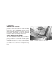
UNDERSTANDING THE FEATURES OF YOUR VEHICLE TO OPEN AND CLOSE THE HOOD To open the hood, pull the release lever inside your vehicle located below the instrument panel and in front of the driver’s door. Then, reach under the hood, move safety latch to the left, and lift the hood. To prevent possible damage, do not slam the hood to close it. Use a firm downward push at the center of the hood to ensure that both latches engage.
UNDERSTANDING THE FEATURES OF YOUR VEHICLE 119 WARNING! If the hood is not fully latched, it could fly up when the vehicle is moving and block your forward vision. Be sure all hood latches are fully latched before driving. LIGHTS Multi-Function Control Lever The multi-function control lever controls the operation of the headlights, turn signals, headlight beam selection, instrument panel light dimming, passing light, interior courtesy/dome lights, and optional fog lights.
UNDERSTANDING THE FEATURES OF YOUR VEHICLE Battery Saver Feature—Exterior/Interior Lights If the multi-function control lever is left in the interior light position, parking light position, or the headlight position when the ignition switch is moved to the OFF position, the battery saver feature will automatically turn off the exterior and interior lights after eight minutes. Normal operation will resume when the ignition is turned ON or when the headlight switch is turned to another position.
UNDERSTANDING THE FEATURES OF YOUR VEHICLE 121 This system performs two functions. With the engine running and the multi-function control lever in the A (Auto) position, the headlights will turn on and off based on the surrounding light levels. Headlights On Automatically With Wipers If your vehicle is equipped with Automatic Headlights it also has this customer programmable feature.
UNDERSTANDING THE FEATURES OF YOUR VEHICLE To Activate 1. Select “Auto Headlamp Low/High Beams? — Low/ High Beam.” Refer to “EVIC — Customer Programmable Features” in Section 4 of this manual. 2. Turn the end of the multi-function control lever to the A (Auto) headlight position. NOTE: This system will not activate until the vehicle is at or above 20 mph (32 km/h). To Deactivate 1. Pull back on the muti-function control lever to manually deactivate the system (normal operation of high beams). 2.
UNDERSTANDING THE FEATURES OF YOUR VEHICLE 123 “Off” position the instrument panel lighting is at the lowest light level and may not be suitable for night driving. Daytime Running Lights — If Equipped The high beam headlights come on at a low intensity level whenever the engine is running, and the transmission is not in the P (Park) position. The lights remain on until the ignition switch is turned OFF or the parking brake is engaged. The headlight switch must be used for normal night time driving.
UNDERSTANDING THE FEATURES OF YOUR VEHICLE Turn Signals Move the multi-function control lever up or down and the arrows on each side of the instrument cluster will flash to show proper operation of the front and rear turn signal lights. You can signal a lane change by moving the lever partially up or down. Turn Signal Auto-Mode Tap the multi-function control lever once and the turn signal (left or right) will flash 3 times, and automatically turn off.
UNDERSTANDING THE FEATURES OF YOUR VEHICLE 125 Interior Lights The interior lighting consists of courtesy lights mounted below the instrument panel, an overhead console light assembly which contains both driver and passenger reading lights, reading lights located above the rear doors, and a rear cargo light. Opening a door or turning the center of the multi-function control lever to the extreme up position will activate all interior courtesy lights.
UNDERSTANDING THE FEATURES OF YOUR VEHICLE WINDSHIELD WIPERS AND WASHERS The front and rear wipers and washers are operated by a switch in the right side control lever. Turn the end of the control lever to select “Lo,” “Hi,” or one of the five speed sensitive intermittent windshield wiper speeds. Refer to “Speed Sensitive Intermittent Wiper System” in this section. For information on the rear wiper and washer refer to “Rear Window Features” in this section.
UNDERSTANDING THE FEATURES OF YOUR VEHICLE 127 To use the washer, pull the lever toward you and hold while spray is desired. If the lever is pulled while in the delay range, the wiper will operate for several seconds after the lever is released, and then resume the intermittent interval previously selected. If the lever is pulled while in the OFF position, the wipers will operate for several wipe cycles, then turn off. WARNING! Sudden loss of visibility through the windshield could lead to an accident.
UNDERSTANDING THE FEATURES OF YOUR VEHICLE Rain Sensing Wipers—If Equipped This feature senses moisture on the windshield and automatically activates the wipers for the driver. The feature is especially useful for road splash or overspray from the windshield washers of the vehicle ahead. Rotate the end of the multi-function lever to one of five settings to activate this feature. The sensitivity of the system can be adjusted with the multi-function lever.
UNDERSTANDING THE FEATURES OF YOUR VEHICLE 129 • A customer programmable feature in the Electronic Vehicle Information Center (EVIC) allows the Rain Sense feature to be turned off. Refer to “Electronic Vehicle Information Center (EVIC) — Customer Programmable Features” in Section 4 of this manual.
UNDERSTANDING THE FEATURES OF YOUR VEHICLE TILT STEERING COLUMN To tilt the column, push down on the lever below the turn signal control and move the wheel up or down, as desired. Pull the lever back towards you and firmly push the lever until it is above the lower surface of the shroud to lock the column in place. WARNING! Tilting the steering wheel column while the vehicle is moving is dangerous. Without a stable steering column, you could lose control of the vehicle and have an accident.
UNDERSTANDING THE FEATURES OF YOUR VEHICLE 131 • The pedals can be adjusted while driving. • The pedals cannot be adjusted when the vehicle is in R (Reverse) or when the Speed Control is ON. A message will be displayed in the Electronic Vehicle Information Center (EVIC) if the pedals are attempted to be adjusted when the system is locked out (“Adjustable Pedal Disabled — Cruise Control Engaged” or “Adjustable Pedal Disabled — Vehicle In Reverse”).
UNDERSTANDING THE FEATURES OF YOUR VEHICLE ELECTRONIC SPEED CONTROL When engaged, this device takes over accelerator operations at speeds greater than 25 mph (40 km/h) for 5.7L engines, and 30 mph (48 km/h) for 3.7L/4.7L engines. The controls are mounted on the steering wheel and consist of ON·OFF, SET, RES·ACCEL, CANCEL, and DECEL controls. To Activate Press the ON·OFF button to turn the system ON. To turn the system OFF, press the ON·OFF button again. The system should be turned OFF when not in use.
UNDERSTANDING THE FEATURES OF YOUR VEHICLE 133 To Resume Speed To resume a previously set speed, press and release the RES·ACCEL button. Resume can be used at any speed above 25 mph (40 km/h) for 5.7L engines, and 30 mph (48 km/h) for 3.7L/4.7L engines. To Vary the Speed Setting When the Speed Control is ON, speed can be increased by pressing and holding the RES·ACCEL button. When the button is released, a new set speed will be established.
UNDERSTANDING THE FEATURES OF YOUR VEHICLE to lock out overdrive. Press the TOW/HAUL switch on the lower center switch bank (below the Heating/Air Conditioning controls). vehicle to gain speed, press the brake pedal, which will disengage the Speed Control and help slow your vehicle. WARNING! WARNING! Leaving the Speed Control ON when not in use is dangerous. You could accidentally set the system or cause it to go faster than you want. You could lose control and have an accident.
UNDERSTANDING THE FEATURES OF YOUR VEHICLE 135 ELECTRONIC BRAKE CONTROL SYSTEM Your vehicle is equipped with an advanced electronic brake control system that includes ABS (Anti-Lock Brake System), TCS (Traction Control System), BAS (Brake Assist System), ERM (Electronic Roll Mitigation), and ESP (Electronic Stability Program). All five systems work together to enhance vehicle stability and control in various driving conditions, and are commonly referred to as ESP.
UNDERSTANDING THE FEATURES OF YOUR VEHICLE TCS (Traction Control System) This system monitors the amount of wheel spin of each of the driven wheels. If wheel spin is detected, brake pressure is applied to the slipping wheel(s) and engine power is reduced to provide enhanced acceleration and stability. A feature of the TCS system functions similar to a limited slip differential and controls the wheel spin across a driven axle.
UNDERSTANDING THE FEATURES OF YOUR VEHICLE 137 WARNING! BAS (Brake Assist System) cannot prevent the natural laws of physics from acting on the vehicle, nor can it increase the traction afforded by prevailing road conditions. BAS cannot prevent accidents, including those resulting from excessive speed in turns, driving on very slippery surfaces, or hydroplaning. Only a safe, attentive, and skillful driver can prevent accidents.
UNDERSTANDING THE FEATURES OF YOUR VEHICLE NOTE: Anytime the ESP system is in the “Full Off” mode, ERM is disabled. Refer to ESP (Electronic Stability Program) for a complete explanation of the available ESP modes. WARNING! Many factors, such as vehicle loading, road conditions and driving conditions, influence the chance that wheel lift or rollover may occur. ERM cannot prevent all wheel lift or rollovers, especially those that involve leaving the roadway or striking objects or other vehicles.
UNDERSTANDING THE FEATURES OF YOUR VEHICLE 139 • Understeer - when the vehicle is turning less than appropriate for the steering wheel position. The ⬙ESP/TCS Indicator Light⬙ located in the instrument cluster, starts to flash as soon as the tires lose traction and the ESP system becomes active. The ⬙ESP/TCS Indicator Light⬙ also flashes when TCS is active. If the ⬙ESP/TCS Indicator Light⬙ begins to flash during acceleration, ease up on the accelerator and apply as little throttle as possible.
UNDERSTANDING THE FEATURES OF YOUR VEHICLE High Range (4WD Models) or 2WD Models On This is the normal operating mode for ESP in 4WD high range and in 2WD vehicles. Whenever the vehicle is started or the transfer case (if equipped) is shifted from 4WD low range or neutral back to 4WD high range, the ESP system will be in this mode. This mode should be used for most all driving situations. ESP should only be turned to “Partial Off” or “Full Off” for specific reasons as noted below.
UNDERSTANDING THE FEATURES OF YOUR VEHICLE 141 NOTE: To improve the vehicle’s traction when driving with snow chains, or starting off in deep snow, sand, or gravel, it may be desirable to switch to the “Partial Off” mode by pressing the ESP switch. Once the situation requiring ESP to be switched to the “Partial Off” mode is overcome, turn ESP back on by momentarily depressing the “ESP Control Switch”. This may be done while the vehicle is in motion.
UNDERSTANDING THE FEATURES OF YOUR VEHICLE WARNING! With the ESP switched off, the enhanced vehicle stability offered by ESP and ERM are unavailable. In an emergency evasive maneuver, the ESP and ERM systems will not engage to assist in maintaining stability. The “Full Off” ESP mode is intended for off-highway or off-road use only. 4WD Low Range Full Off This is the normal operating mode for ESP in 4WD low range.
UNDERSTANDING THE FEATURES OF YOUR VEHICLE 143 WARNING! With the ESP switched off, the enhanced vehicle stability offered by ESP and ERM are unavailable. In an emergency evasive maneuver, the ESP and ERM systems will not engage to assist in maintaining stability. The “Full Off” mode is intended for offhighway or off-road use only. ESP/BAS Warning Lamp and ESP/TCS Indicator Light The malfunction indicator lamp for the ESP is combined with the BAS indicator.
UNDERSTANDING THE FEATURES OF YOUR VEHICLE REAR PARK ASSIST SYSTEM— IF EQUIPPED The Rear Park Assist System provides visual and audible indications of the distance between the rear fascia and the detected obstacle when backing up. Refer to the Warning Section and Note Section for limitations of this system and recommendations. The Rear Park Assist System will remember the last system state (enabled or disabled) from the last ignition cycle when the ignition is changed to the RUN/ON position.
UNDERSTANDING THE FEATURES OF YOUR VEHICLE 145 Rear Park Assist Warning Display The Rear Park Assist Warning Display, located in the headliner near the flipper glass, provides both visual and audible warnings to indicate the distance between the rear fascia and the detected obstacle. When the ignition is changed to the RUN/ON position, the warning display will turn ON all of its LEDs for about 1 second. Each side of the warning display has 6 yellow and 2 red LEDs.
UNDERSTANDING THE FEATURES OF YOUR VEHICLE When the detected obstacle is about 11.8 inches (30 cm) from the rear fascia, the warning display will actuate a continuous tone for about 10 seconds, and it will turn ON all 8 LEDs, including both RED LEDs, on the corresponding side of the display. The radio will be muted while the tone is actuated.
UNDERSTANDING THE FEATURES OF YOUR VEHICLE 147 When the switch is pressed to disable the system, the instrument cluster will display the ⬙PARK ASSIST DISABLED⬙ message. Refer to “Electronic Vehicle Information Center (EVIC)” in Section 4 of this manual. When the shifter is changed to R (Reverse) and the system is disabled, the instrument cluster will actuate a single chime, once per ignition cycle, and it will display the message.
UNDERSTANDING THE FEATURES OF YOUR VEHICLE CAUTION! WARNING! • The Rear Park Assist System is only a parking aid and it is unable to recognize every obstacle, including small obstacles. Parking curbs might be temporarily detected or not detected at all. Obstacles located above or below the sensors will not be detected when they are in close proximity. • The vehicle must be driven slowly when using the Rear Park Assist System to be able to stop in time when the obstacle is detected.
UNDERSTANDING THE FEATURES OF YOUR VEHICLE 149 NOTE: Clean all four Rear Park Assist Sensors regularly, taking care not to scratch or damage them. The sensors must not be covered with ice, snow, slush, mud, dirt or debris. Failure to do so can result in the system not working properly. The system might not detect an obstacle behind the fascia or it could provide a false indication that an obstacle is behind the fascia.
UNDERSTANDING THE FEATURES OF YOUR VEHICLE Turning the Rear Camera On Turning the Rear Camera Off 1. To access the rear camera mode, select “Rear Camera” at the Systems Settings screen and press ENTER. Refer to your “Navigation User’s Manual” for detailed operating instructions. 1. To turn the rear camera off, select “Rear Camera” at the Systems Settings screen and press ENTER. Refer to your “Navigation User’s Manual” for detailed operating instructions. 2. Select “ON” at the “Rear Camera” screen.
UNDERSTANDING THE FEATURES OF YOUR VEHICLE 151 OVERHEAD CONSOLE — IF EQUIPPED The overhead console contains an optional universal garage door opener (HomeLink威), storage for sunglasses, and optional power sunroof switches. GARAGE DOOR OPENER — IF EQUIPPED The HomeLink威 Universal Transceiver replaces up to three remote controls (hand held transmitters) that operate devices such as garage door openers, motorized gates, or home lighting. It triggers these devices at the push of a button.
UNDERSTANDING THE FEATURES OF YOUR VEHICLE WARNING! WARNING! A moving garage door can cause injury to people and pets in the path of the door. People or pets could be seriously or fatally injured. Only use this transceiver with a garage door opener that has a “stop and reverse” feature as required by federal safety standards. This includes most garage door opener models manufactured after 1982. Do not use a garage door opener without these safety features it could cause injury or death.
UNDERSTANDING THE FEATURES OF YOUR VEHICLE 153 Programming HomeLink NOTE: When programming a garage door opener, it is advised to park outside the garage. It is also recommended that a new battery be placed in the hand-held transmitter of the device being programmed to HomeLink for quicker training and accurate transmission of the radio-frequency signal. 3 The Electronic Vehicle Information Center (EVIC) features a driver-interactive display which includes HomeLink system messages.
UNDERSTANDING THE FEATURES OF YOUR VEHICLE 1. Press and hold the two outer HomeLink buttons, and release only when the EVIC display shows “CHANNELS CLEARED” (after 20 seconds). Do not hold the buttons for longer than 30 seconds and do not repeat step one to program a second and/or third hand-held transmitter to the remaining two HomeLink buttons. 2. Position the end of your hand-held transmitter 1-3 inches (3-8 cm) away from the HomeLink buttons. 3.
UNDERSTANDING THE FEATURES OF YOUR VEHICLE 155 5. Press and hold the just trained HomeLink button and observe the EVIC display. If the EVIC display shows “CHANNEL X TRANSMIT” (where X is Channel 1, 2, or 3), programming is complete and your device should activate when the HomeLink button is pressed and released. NOTE: To program the remaining two HomeLink buttons, begin with ⬙Programming⬙ step two. Do not repeat step one.
UNDERSTANDING THE FEATURES OF YOUR VEHICLE NOTE: To program the remaining two HomeLink buttons, begin with ⬙Programming⬙ step two. Do not repeat step one. For questions or comments, please contact HomeLink at www.homelink.com or 1-800-355-3515. Canadian Programming/Gate Programming Canadian radio-frequency laws require transmitter signals to ⬙time-out⬙ (or quit) after several seconds of transmission which may not be long enough for HomeLink to pick up the signal during programming.
UNDERSTANDING THE FEATURES OF YOUR VEHICLE 157 Erasing HomeLink Buttons To erase programming from the three buttons (individual buttons cannot be erased but can be ⬙reprogrammed⬙ note below), follow the step noted: • Press and hold the two outer HomeLink buttons and release only when the EVIC display shows “CHANNELS CLEARED” (after 20 seconds). Release both buttons. Do not hold for longer that 30 seconds.
UNDERSTANDING THE FEATURES OF YOUR VEHICLE • This device must accept any interference that may be received including interference that may cause undesired operation. NOTE: Changes or modifications not expressly approved by the party responsible for compliance could void the user’s authority to operate the equipment. HomeLink威 is a trademark owned by Johnson Controls, Inc. POWER SUNROOF — IF EQUIPPED The power sunroof switch is located on the overhead console.
UNDERSTANDING THE FEATURES OF YOUR VEHICLE 159 WARNING! • Never leave children in a vehicle, with the keys in the ignition switch. Occupants, particularly unattended children, can become entrapped by the power sunroof while operating the power sunroof switch. Such entrapment may result in serious injury or death. • In an accident, there is a greater risk of being thrown from a vehicle with an open sunroof. You could also be seriously injured or killed.
UNDERSTANDING THE FEATURES OF YOUR VEHICLE Pinch Protect Override If a known obstruction (ice, debris, etc.) prevents closing, press the switch forward and hold for two seconds after the reversal occurs. This allows the sunroof to move towards the closed position. NOTE: Pinch protection is disabled while the switch is pressed. Venting Sunroof - Express Press and release the ⬙V⬙ button, and the sunroof will open to the vent position.
UNDERSTANDING THE FEATURES OF YOUR VEHICLE 161 Sunroof Maintenance Use only a non-abrasive cleaner and a soft cloth to clean the glass panel. NOTE: Hold onto shade handle until shade is completely open or closed. Ignition Off Operation The power sunroof switches remain active for 10 minutes after the ignition switch has been turned off. Opening either front door will cancel this feature. 3 Sunroof Fully Closed Press the switch forward and release to ensure that the sunroof is fully closed.
UNDERSTANDING THE FEATURES OF YOUR VEHICLE POWER OUTLET To the right of the convenience tray (lower center of instrument panel) is an outlet for electrically powered accessories. Pull lightly on the tab of the plastic cover to access the outlet. Rear Power Outlet The power outlets are a direct feed from the battery so they receive power whether the ignition is in the ON or OFF position. Front Power Outlet The rear power outlet (if equipped) is located in the left rear cargo area.
UNDERSTANDING THE FEATURES OF YOUR VEHICLE 163 CAUTION! Electrical Outlet Use With Engine Off • Many accessories that can be plugged in draw power from the vehicle’s battery, even when not in use (i.e., cellular phones, etc.). Eventually, if plugged in long enough, the vehicle’s battery will discharge sufficiently to degrade battery life and/or prevent engine starting. • Accessories that draw higher power (i.e., coolers, vacuum cleaners, lights, etc.) will degrade the battery even more quickly.
UNDERSTANDING THE FEATURES OF YOUR VEHICLE cup depression towards the passenger seat, but the top surface will not be flush with the console surface. Cup Holders (Second Row Seat) The second row seat has two cup holders in the center armrest. Lower the center armrest. Refer to “Seats” in this section. Press the front of the cup holder, and the cup holder will come out of the armrest. Cup Holders (Third Row Seat) The third row seat passengers have cup holders on the left and right rear trim panels.
UNDERSTANDING THE FEATURES OF YOUR VEHICLE 165 CARGO AREA FEATURES Cargo Load Floor The panel in the load floor is reversible for added utility. One side is carpeted and the other side features a plastic lined tray which holds a variety of items. 3 The cargo load floor is held by spring loaded latches. In order to use the cargo load floor, use the following procedure: Rear Storage Cover NOTE: The cargo load floor latches should not be used as cargo tie-downs. 1.
UNDERSTANDING THE FEATURES OF YOUR VEHICLE 2. Pull up on loop(s) and twist 90 degrees, so they are parallel to the slotted hole in tray. 5. Push loop(s) back down, so they are parallel to the top of the tray. 3. Lift tray over loop(s), and reposition tray. REAR WINDOW FEATURES Rear Window Wiper/Washer A switch on the right side of the steering column controls operation of the rear wiper/washer function.
UNDERSTANDING THE FEATURES OF YOUR VEHICLE 167 the rear wiper switch or the ignition switch needs to be turned OFF and ON to restart the rear wiper. Adding Washer Fluid The fluid reservoir for the windshield washers and the rear window washer is shared. It is located in the front of the engine compartment on the passenger side and should be checked for fluid level at regular intervals.
UNDERSTANDING THE FEATURES OF YOUR VEHICLE CAUTION! To avoid damaging the electrical conductors of the rear window defroster, do not use scrapers, sharp instruments, or abrasive window cleaners on the interior surface of the window. Labels can be peeled off after soaking with warm water. ROOF LUGGAGE RACK — IF EQUIPPED External racks do not increase the total load carrying capacity of the vehicle.
UNDERSTANDING THE FEATURES OF YOUR VEHICLE 169 NOTE: If the rear cross rail (or any metallic object) is placed over the satellite radio antenna (if equipped), you may experience interruption of satellite radio reception. For improved satellite radio reception, place the rear cross rail in detent position #4 when not in use. CAUTION! • To prevent damage to the roof of your vehicle, DO NOT carry any loads on the roof rack without cross rails installed.
UNDERSTANDING THE FEATURES OF YOUR VEHICLE WARNING! Cargo must be securely tied before driving your vehicle. Improperly secured loads can fly off the vehicle, particularly at high speeds, resulting in personal injury or property damage. Follow the roof rack “Cautions” when carrying cargo on your roof rack.
UNDERSTANDING YOUR INSTRUMENT PANEL CONTENTS 䡵 Instrument Panel And Controls . . . . . . . . . . . . . 174 ▫ Radio Broadcast Signals . . . . . . . . . . . . . . . . . 197 䡵 Instrument Cluster . . . . . . . . . . . . . . . . . . . . . . 175 ▫ Two Types Of Signals . . . . . . . . . . . . . . . . . . 198 䡵 Instrument Cluster Description . . . . . . . . . . . . . 176 ▫ Electrical Disturbances . . . . . . . . . . . . . . . . . . 198 䡵 Electronic Vehicle Information Center — If Equipped . . . . . . . . . .
UNDERSTANDING YOUR INSTRUMENT PANEL ▫ Operation Instructions (CD Mode For CD Audio Play) . . . . . . . . . . . 204 ▫ Operating Instructions - Hands Free Phone — If Equipped . . . . . . . . . . . . . . . . . . . . . . . . . 220 ▫ Load/Eject Button (CD Mode For CD Audio Play) . . . . . . . . . . . 206 ▫ Operating Instructions - Satellite Radio — If Equipped . . . . . . . . . . . . . . . . . . . . . . . . . 220 ▫ Notes On Playing MP3 Files . . . . . . . . . . . . .
UNDERSTANDING YOUR INSTRUMENT PANEL 173 ▫ Electronic Serial Number/Sirius Identification Number (ESN/SID) . . . . . . . . . . . . . . . . . . . . 227 ▫ Selecting Satellite Mode In REF Radios . . . . . . 228 ▫ Selecting Satellite Mode In RAQ Radios . . . . . 228 ▫ Selecting a Channel . . . . . . . . . . . . . . . . . . . . 228 ▫ Storing And Selecting Pre-Set Channels . . . . . . 229 ▫ Using The PTY (Program Type) Button — If Equipped . . . . . . . . . . . . . . . . . . . . . . . . . 229 ▫ Radio Operation .
UNDERSTANDING YOUR INSTRUMENT PANEL INSTRUMENT PANEL AND CONTROLS
UNDERSTANDING YOUR INSTRUMENT PANEL 175 INSTRUMENT CLUSTER 4
UNDERSTANDING YOUR INSTRUMENT PANEL INSTRUMENT CLUSTER DESCRIPTION 1. Speedometer Indicates vehicle speed. 2. Brake Warning Light The BRAKE warning light will come on when the ignition is first turned on, and stay on briefly as a bulb check. If the bulb does not come on during starting, have the bulb repaired promptly. If the light stays on longer, it may be an indication that the parking brake has not been released.
UNDERSTANDING YOUR INSTRUMENT PANEL 177 engine start. If the bulb does not come on when turning the key from OFF to ON, have the condition checked promptly. during starting, stays on, or turns on while driving, have the system inspected by an authorized dealer as soon as possible. Certain conditions such as a loose or missing gas cap, poor fuel quality, etc. may illuminate the light after engine start. The vehicle should be serviced if the light stays on through several of your typical driving cycles.
UNDERSTANDING YOUR INSTRUMENT PANEL 8. Tachometer The red segments indicate the maximum permissible engine revolutions-per-minute (r.p.m. x 1000) for each gear range. Before reaching the red area, ease up on the accelerator. 9. Security Alarm System Indicator Light — If Equipped This light will flash rapidly for approximately 15 seconds when the vehicle theft alarm is arming. The light will flash at a slower speed continuously after the alarm is set.
UNDERSTANDING YOUR INSTRUMENT PANEL 179 12. Tire Pressure Monitoring Telltale Light Each tire, including the spare (if provided), should be checked monthly when cold and inflated to the inflation pressure recommended by the vehicle manufacturer on the vehicle placard or tire inflation pressure label. (If your vehicle has tires of a different size than the size indicated on the vehicle placard or tire inflation pressure label, you should determine the proper tire inflation pressure for those tires.
UNDERSTANDING YOUR INSTRUMENT PANEL CAUTION! The TPMS has been optimized for the original equipment tires and wheels. TPMS pressures and warning have been established for the tire size equipped on your vehicle. Undesirable system operation or sensor damage may result when using replacement equipment that is not of the same size, type, and/or style. After-market wheels can cause sensor damage.
UNDERSTANDING YOUR INSTRUMENT PANEL 181 WARNING! A hot engine cooling system is dangerous. You or others could be badly burned by steam or boiling coolant. If you decide to look under the hood yourself, refer to Section 7 of this manual. Follow the warnings under “Cooling System Pressure Cap.” 14. Electronic Vehicle Information Center Display When the appropriate conditions exist, this display shows the Electronic Vehicle Information Center (EVIC) messages.
UNDERSTANDING YOUR INSTRUMENT PANEL 18. Seat Belt Reminder Light When the ignition switch is first turned ON, this light will turn on for 5 to 8 seconds as a bulb check. During the bulb check, if the driver’s seat belt is unbuckled, a chime will sound. After the bulb check or when driving, if the driver or front passenger seat belt remains unbuckled, the Seat Belt Warning Light will flash or remain on continuously.
UNDERSTANDING YOUR INSTRUMENT PANEL 183 is placed in the P (Park) position. The light should turn off. If the light remains lit with the engine running your vehicle will usually be drivable, however, see your dealer for service as soon as possible. If the light is flashing when the engine is running, immediate service is required and you may experience reduced performance, an elevated/rough idle or engine stall and your vehicle may require towing.
UNDERSTANDING YOUR INSTRUMENT PANEL ELECTRONIC VEHICLE INFORMATION CENTER — IF EQUIPPED • TURN SIGNAL ON • PERFORM SERVICE • KEY NOT PROGRAMMED — DAMAGED KEY • KEY NOT PROGRAMMED — INVALID KEY • KEY NOT PROGRAMMED — EXCEEDED KEY PROGRAM LIMIT • PROGRAMMING ACTIVE — NEW KEY PROGRAMMED • SERVICE SECURITY KEY • INVALID KEY — TRY ALTERNATE KEY The electronic vehicle information center (EVIC) located in the instrument cluster, when the appropriate conditions exist, will display the following messages and
UNDERSTANDING YOUR INSTRUMENT PANEL 185 • LIFTGATE/DOOR OPEN (with graphic) • LIFTGLASS/HOOD OPEN (with graphic) • LIFTGATE/DOORS OPEN (with graphic) • WASHER FLUID LOW (with graphic) • LIFTGLASS OPEN (with graphic) • CHECK GAUGES • HOOD OPEN (with graphic) • AUTO HIGHBEAM ON • HOOD/DOOR OPEN (with graphic) • AUTO HIGHBEAM OFF • HOOD/DOORS OPEN (with graphic) • PARK ASSIST DISABLED • LIFTGATE/HOOD OPEN (with graphic) • SERVICE PARK ASSIST SYSTEM • HOOD/GLASS/DOOR OPEN (with graphic) • TRANSM
UNDERSTANDING YOUR INSTRUMENT PANEL • CHECK GAS CAP • SERVICE TIRE PRESS SYSTEM • ESP OFF • LEFT FRONT LOW PRESSURE (Premium TPM System Only) • MEMORY #1 POSITIONS SET • MEMORY #2 POSITIONS SET • MEMORY SYSTEM DISABLED — SEATBELT FASTENED (with graphic) • MEMORY SYSTEM DISABLED — VEHICLE NOT IN PARK • DRIVER 1 MEMORY • DRIVER 2 MEMORY • PEDAL ADJUST DISABLED — CRUISE CONTROL SET • PEDAL ADJUST DISABLED — SHIFTER IN REVERSE • RIGHT FRONT LOW PRESSURE (Premium TPM System Only) • LEFT REAR LOW PRESSU
UNDERSTANDING YOUR INSTRUMENT PANEL 187 Customer Programmable Features Press the MENU button until one of the display choices following appears: Language? When in this display you may select one of three languages for all display nomenclature, including the trip computer functions. Press the STEP button while in this display selects English, Espanol, or Francais. As you continue the displayed information will be shown in the selected language.
UNDERSTANDING YOUR INSTRUMENT PANEL Display U.S. or Metric? Pressing the STEP button when in this display selects US or Metric. The overhead console and instrument panel displays will be in the selected units. Auto Door Locks? When this feature is selected, all doors and the liftgate lock automatically when the speed of the vehicle reaches 15 mph (25 km/h). Pressing the STEP button when in this display will select “Yes” or “No.
UNDERSTANDING YOUR INSTRUMENT PANEL 189 Sound Horn With Lock? When this feature is selected a short horn sound will occur when the remote keyless entry “Lock” button is pressed. This feature may be selected with or without the flash lights on lock/unlock feature. Pressing the STEP button when in this display will select “Yes” or “No.
UNDERSTANDING YOUR INSTRUMENT PANEL Headlamps On With Wipers? (Available with Auto Headlights Only) When this feature is selected and the headlight switch has at least once been moved to the A (Auto) position, the headlights will turn on when the wipers are turned on. The headlights will also turn off when the wipers are turned off if they were turned on in this way. Pressing the STEP button when in this display will select “Yes” or “No.
UNDERSTANDING YOUR INSTRUMENT PANEL 191 Easy Entry/Exit Seat? (Available with Memory Seat Only) This feature provides automatic driver’s seat positioning which will enhance driver mobility out of and into the vehicle. The Easy Entry/ Easy Exit feature is not enabled when the vehicle is delivered from the factory. The Easy Entry/ Easy Exit feature is enabled (or later disabled) through the programmable features in the Electronic Vehicle Information Center (EVIC).
UNDERSTANDING YOUR INSTRUMENT PANEL WARNING! Even if the display still reads a few degrees above 32°F ( 0°C), the road surface may be icy, particularly in woods or on bridges. Drive carefully under such conditions to prevent an accident and possible personal injury or property damage.
UNDERSTANDING YOUR INSTRUMENT PANEL 193 Trip Computer This feature, located in the instrument cluster, displays the following information when the display is in the “Compass/Temperature” mode and the STEP button is pressed: Step Button Press the STEP button to cycle through all of the Compass/Mini-Trip Computer displays.
UNDERSTANDING YOUR INSTRUMENT PANEL Reset Button Press the RESET button to reset the display you are in. Press and hold the RESET button (for 2 seconds) to reset all of the displays. Average Fuel Economy Shows the average fuel economy since the last reset. When the fuel economy is reset, the display will read “RESET” or show dashes for two seconds. Then, the history information will be erased, and the averaging will continue from the last fuel average reading before the reset.
UNDERSTANDING YOUR INSTRUMENT PANEL 195 Elapsed Time Shows the accumulated ignition ON time since the last reset. Tire Pressure Display — If Equipped Shows the current pressure of all 4 road tires. NOTE: Tires heat up during normal driving conditions. Heat will cause the tire pressure to increase from 2 to 6 psi (14 to 41 kPa) during normal driving conditions. Refer to “Tire Inflation Pressures” in Section 5 for additional information. Miles to Service Shows the distance remaining to require service.
UNDERSTANDING YOUR INSTRUMENT PANEL NOTE: To ensure proper compass calibration, make sure the compass variance is properly set before manually calibrating the compass. Refer to Variance Map. To Put Into a Calibration Mode Start the engine and leave the transmission in the P (Park) position. Set the display to “Compass/Temperature.
UNDERSTANDING YOUR INSTRUMENT PANEL 197 To set the variance: Turn the ignition ON and set the display to “Compass/Temperature.” Press the C/T button for approximately 5 seconds. The last variance zone number will be displayed. Press and hold the STEP button for 1 second to select the new variance zone and press the RESET button to resume normal operation. RADIO GENERAL INFORMATION Radio Broadcast Signals Your new radio will provide excellent reception under most operating conditions.
UNDERSTANDING YOUR INSTRUMENT PANEL Two Types of Signals There are two basic types of radio signals... AM or Amplitude Modulation, in which the transmitted sound causes the amplitude, or height, of the radio waves to vary... and FM or Frequency Modulation, in which the frequency of the wave is varied to carry the sound. Electrical Disturbances Radio waves may pick up electrical disturbances during transmission. They mainly affect the wave amplitude, and thus remain a part of the AM reception.
UNDERSTANDING YOUR INSTRUMENT PANEL 199 SALES CODE RAQ – AM/FM/CD (6-DISC) RADIO WITH OPTIONAL SATELLITE RADIO, HANDS FREE PHONE, AND VEHICLE ENTERTAINMENT SYSTEMS (VES) CAPABILITIES NOTE: The radio sales code is located on the lower right side of your radio faceplate. Operating Instructions - Radio Mode NOTE: The ignition switch must be in the ON or ACC position to operate the radio. Power Switch/Volume Control (Rotary) Press the ON/VOL control to turn the radio ON.
UNDERSTANDING YOUR INSTRUMENT PANEL Mode Button (Radio Mode) Press the mode button repeatedly to select between the CD player, Satellite Radio, or Vehicle Entertainment System (VES) (if equipped). SEEK Button (Radio Mode) Press and release the SEEK button to search for the next listenable station in either AM/FM or Satellite (if equipped) mode. Press the right side of the button to seek up and the left side to seek down. The radio will remain tuned to the new station until you make another selection.
UNDERSTANDING YOUR INSTRUMENT PANEL 201 Time Button Press the time button and the time of day will be displayed for 5 seconds. Clock Setting Procedure 1. Press and hold the time button until the hours blink. 2. Adjust the hours by turning the right side Tune / Audio control. 3. After the hours are adjusted, press the right side Tune / Audio control to set the minutes. The minutes will begin to blink. 4. Adjust the minutes using the right side Tune / Audio control. 5.
UNDERSTANDING YOUR INSTRUMENT PANEL Press the rotary TUNE control a third time and TREBLE will display. Turn the TUNE control to the right or left to increase or decrease the Treble tones. turning the TUNE rotary knob within 5 seconds will allow the program format type to be selected. Many radio stations do not currently broadcast PTY information. Press the rotary TUNE control a fourth time and BALANCE will display.
UNDERSTANDING YOUR INSTRUMENT PANEL 203 Jazz News Nostalgia Oldies Personality Public Rhythm and Blues Religious Music Religious Talk Rock Soft Soft Rock Soft Rhythm and Blues Sports Talk Top 40 Weather Jazz News Nostalgia Oldies Personality Public Rhythm_and_Blues Religious_Music Religious_Talk Rock Soft Soft_Rock Soft_R_&_B Sports Talk Top_40 Weather By pressing the SEEK button when the PTY icon is displayed, the radio will be tuned to the next frequency station with the same selected PTY name.
UNDERSTANDING YOUR INSTRUMENT PANEL You may add a second station to each push-button by repeating the above procedure with this exception: Press the SET/DIR button twice and SET 2 will show in the display window. Each button can be set for SET 1 and SET 2 in both AM and FM. This allows a total of 12 AM,12 FM and 12 Satellite (if equipped) stations to be stored into push-button memory. The stations stored in SET 2 memory can be selected by pressing the push-button twice.
UNDERSTANDING YOUR INSTRUMENT PANEL 205 CAUTION! This CD player will accept 4 3/4 inch (12 cm) discs only. The use of other sized discs may damage the CD player mechanism. You may eject a disc with the radio OFF. If you insert a disc with the ignition ON and the radio ON, the unit will switch from radio to CD mode and begin to play when you insert the disc. The display will show the disc number, the track number, and index time in minutes and seconds. Play will begin at the start of track 1.
UNDERSTANDING YOUR INSTRUMENT PANEL LOAD/EJECT Button (CD Mode for CD Audio Play) Radio display will show ⬙EJECTING DISC⬙ when the disc is being ejected and prompt the user to remove the disc. LOAD/ EJECT - Load Press the LOAD/ EJECT button and the pushbutton with the corresponding number where the CD is being loaded. The radio will display PLEASE WAIT and prompt when to INSERT DISC. After the radio displays ⬙LOAD DISC⬙ insert the CD into the player.
UNDERSTANDING YOUR INSTRUMENT PANEL 207 TIME Button (CD MODE for CD Audio Play) Press this button to change the display from a large CD playing time display to a small CD playing time display. RW/FF (CD MODE for CD Audio Play) Press and hold FF (Fast Forward) and the CD player will begin to fast forward until FF is released or RW or another CD button is pressed. The RW (Reverse) button works in a similar manner.
UNDERSTANDING YOUR INSTRUMENT PANEL Notes On Playing MP3 Files The radio can play MP3 files, however, acceptable MP3 file recording media and formats are limited. When writing MP3 files, pay attention to the following restrictions. Supported Media (Disc Types) The MP3 file recording media supported by the radio are CD-ROM, CD-R and CD-RW. Supported Medium Formats (File Systems) The medium formats supported by the radio are ISO 9660 Level 1 and Level 2 and includes the Joliet extension.
UNDERSTANDING YOUR INSTRUMENT PANEL 209 Supported MP3 File Formats The radio will recognize only files with the *.mp3 extension as MP3 files. Non-MP3 files named with the *.mp3 extension may cause playback problems. The radio is designed to recognize the file as an invalid MP3 and will not play the file. When using the MP3 encoder to compress audio data to an MP3 file, the bit rate and sampling frequencies in the following table are supported. In addition, variable bit rates (VBR) are also supported.
UNDERSTANDING YOUR INSTRUMENT PANEL Playback of MP3 Files When a medium containing MP3 data is loaded, the radio checks all files on the medium. If the medium contains a lot of folders or files, the radio will take more time to start playing the MP3 files.
UNDERSTANDING YOUR INSTRUMENT PANEL 211 LOAD / EJECT - Eject Press the LOAD/ EJECT button and the pushbutton with the corresponding number where the CD was loaded and the disc will unload and move to the entrance for easy removal. Radio display will show ⬙EJECTING DISC⬙ when the disc is being ejected and prompt the user to remove the disc. If you have ejected a disc and have not removed it within 15 seconds, it will be reloaded. If the CD is not removed, the radio will continue to play the non-removed CD.
UNDERSTANDING YOUR INSTRUMENT PANEL AM/FM Button (CD Mode for MP3 Play) Switches back to Radio mode. RND/ PTY Button (CD Mode for MP3 Play) Pressing this button plays files randomly. SET/DIR Button (CD Mode for MP3 Play) Press the SET/DIR Button to display folders, when playing an MP3 discs that have a file/folder structure. Turn the TUNE control to display available folders or move through available folders. Press the TUNE control to select a folder.
UNDERSTANDING YOUR INSTRUMENT PANEL 213 SALES CODE REF — AM/FM/CD (SINGLE DISC) RADIO WITH OPTIONAL SATELLITE RADIO AND HANDS FREE PHONE CAPABILITY NOTE: The radio sales code is located on the lower right side of your radio faceplate. Operating Instructions - Radio Mode NOTE: The ignition switch must be in the ON or ACC position to operate the radio. Power Switch/Volume Control (Rotary) Press the ON/VOL control to turn the radio ON. Press the ON/VOL a second time to turn OFF the radio.
UNDERSTANDING YOUR INSTRUMENT PANEL Mode Button (Radio Mode) Press the mode button repeatedly to select between the CD player and Satellite Radio (if equipped). SEEK Button (Radio Mode) Press and release the SEEK button to search for the next listenable station in either AM/FM or Satellite (if equipped) mode. Press the right side of the button to seek up and the left side to seek down. The radio will remain tuned to the new station until you make another selection.
UNDERSTANDING YOUR INSTRUMENT PANEL 215 Clock Setting Procedure 1. Press and hold the time button until the hours blink. 2. Adjust the hours by turning the right side Tune/ Audio control. 3. After the hours are adjusted, press the right side Tune/Audio control to set the minutes. The minutes will begin to blink. 4. Adjust the minutes using the right side Tune/Audio control. 5. To exit, press any button/knob or wait 5 seconds.
UNDERSTANDING YOUR INSTRUMENT PANEL Press the rotary TUNE control a fourth time and BAL will display. Turn the TUNE control to the right or left to adjust the sound level from the right or left side speakers. selected within 5 seconds after pressing the SET button, the station will continue to play but will not be stored into push-button memory. Press the rotary TUNE control a fifth time and FADE will display.
UNDERSTANDING YOUR INSTRUMENT PANEL 217 Operation Instructions - CD Mode NOTE: The ignition switch must be in the ON or ACC position to operate the radio. Inserting The Compact Disc (Single CD Player) Gently insert one CD into the CD player with the CD label facing up. The CD will automatically be pulled into the CD Player and the CD icon will illuminate on the radio display. If the volume control is ON, the unit will switch to CD mode and begin to play.
UNDERSTANDING YOUR INSTRUMENT PANEL SCAN Button (CD Mode) Press this button to play the first 10 seconds of each track. To stop the scan function, press the button a second time. EJECT Button (CD Mode) Press this button and the disc will unload and move to the entrance for easy removal. The unit will switch to the last selected mode. If you do not remove the disc within 15 seconds, it will be reloaded. The radio mode will continue to appear.
UNDERSTANDING YOUR INSTRUMENT PANEL 219 Operation Instructions - Auxiliary Mode The auxiliary (AUX) jack is an audio input jack, which allows the user to plug in a portable device such as an MP3 player, cassette player, or microphone and utilize the vehicle’s audio system to amplify the source and play through the vehicle speakers. MUTE Button (Auxiliary Mode) Press the MUTE button to cancel the sound from the speakers. ⬙MUTE⬙ will display.
UNDERSTANDING YOUR INSTRUMENT PANEL TIME Button (Auxiliary Mode) Press this button to change the display from elapsed playing time to time of day. The time of day will display for 5 seconds. Operating Instructions - Satellite Radio — If Equipped Refer to the “Satellite Radio” section of the Owner’s Manual. RW/FF (Auxiliary Mode) No function. SALES CODE REC — AM/FM/CD (6–DISC) RADIO WITH NAVIGATION SYSTEM RND/SET Button (Auxiliary Mode) No function.
UNDERSTANDING YOUR INSTRUMENT PANEL 221 Satellite Navigation Radio with CD Player with MP3 Capability (REC) - combines a Global-Positioning System-based navigation system with an integrated color screen to provide maps, turn identification, selection menus and instructions for selecting a variety of destinations and routes, AM/FM stereo radio and six-disc CD changer with MP3 capability. Mapping information for navigation is supplied on a DVD that is loaded into the unit.
UNDERSTANDING YOUR INSTRUMENT PANEL 1. At the Main Menu screen, highlight “Clock Setup” and press ENTER OR press and hold for 3 seconds the TIME button on the unit’s faceplate. The Clock Setup screen appears. 2. To show the GPS clock, select “Displayed Clock: GPS Clock” and press ENTER. 3. To adjust the time zone, Select “Time Zone” and press ENTER. Select the appropriate time zone and press ENTER. 4. To turn daylight savings on or off, select “Daylight Savings” and press ENTER.
UNDERSTANDING YOUR INSTRUMENT PANEL 223 1. At the Clock Setup screen highlight “Displayed Clock: User Defined Clock”. 3. To decrease the clock by one hour, use the Select Encoder to highlight the “-” sign. Press ENTER. Press ENTER again to decrease the clock by another hour. 4. To increase the clock by minutes, make sure “MIN +” is highlighted and press ENTER. Press ENTER again to increase the clock by another minute. 5. To decrease the clock by minutes, use the Select Encoder to highlight the “-“ sign.
UNDERSTANDING YOUR INSTRUMENT PANEL Audio Clock Display Select this option to change the size of the clock on the audio screens. 3. To switch the clock to the small clock, quickly press TIME again. 1. When you are at an audio screen, quickly press the TIME button on the navigation faceplate. 2. In this example the large clock appears on the screen. 4. To toggle back to the large clock, simply press TIME.
UNDERSTANDING YOUR INSTRUMENT PANEL 225 VIDEO ENTERTAINMENT SYSTEM (SALES CODE XRV) — IF EQUIPPED The optional VES™ (Video Entertainment System) consists of a DVD player and LCD (liquid crystal display) screen, a battery-powered remote control, and two headsets. The DVD player is mounted in the rear of the center console storage bin, and is concealed by a door that lifts up for access. Refer to your VES™ User’s Manual for detailed operating instructions.
UNDERSTANDING YOUR INSTRUMENT PANEL The LCD screen is located on the headliner behind the front seats. Remote Control Location Lowering the Display Screen SATELLITE RADIO — IF EQUIPPED Satellite radio uses direct satellite to receiver broadcasting technology to provide clear digital sound, coast to coast. The subscription service provider is Sirius™ Satellite Radio.
UNDERSTANDING YOUR INSTRUMENT PANEL 227 System Activation To activate your Sirius Satellite Radio service, call the toll-free number 888-539-7474, or visit the Sirius web site at www.sirius.com. Please have the following information available when activating your system: 1. The Electronic Serial Number/Sirius Identification Number (ESN/SID). 2. Credit card information. 3. Your Vehicle Identification Number.
UNDERSTANDING YOUR INSTRUMENT PANEL ESN/SID Access with RAQ Radios With the ignition switch in the ACCESSORY position and the radio OFF, press the CD Eject and TIME buttons simultaneously for 3 seconds. All twelve ESN/SID numbers will be displayed. The radio will exit the ESN/SID mode when any other button is pushed, the ignition is turned OFF, or 5 minutes has passed since any button was pushed. Selecting Satellite Mode in REF Radios Press the MODE button repeatedly until ⬙S A⬙ appears in the display.
UNDERSTANDING YOUR INSTRUMENT PANEL 229 NOTE: Channels that may contain objectionable content can be blocked. Contact Sirius Customer Care at 888-5397474 to discuss options for channel blocking or unblocking. Please have your ESN/SID information available. Storing and Selecting Pre-Set Channels In addition to the 10 AM and 10 FM pre-set stations, you may also commit 10 satellite stations to push button memory. These satellite channel pre-set stations will not erase any AM or FM pre-set memory stations.
UNDERSTANDING YOUR INSTRUMENT PANEL Satellite Antenna To ensure optimum reception on vehicles available with a luggage rack, do not place items on the roof around the rooftop antenna location. Metal objects placed within the line of sight of the antenna will cause decreased performance. Larger luggage items should be placed as far forward as possible. Do not place items directly on or above the antenna. Reception Quality Satellite reception may be interrupted due to one of the following reasons.
UNDERSTANDING YOUR INSTRUMENT PANEL 231 The right hand control is a rocker type switch with a push-button in the center and controls the volume and mode of the sound system. Pressing the top of the rocker switch will increase the volume and pressing the bottom of the rocker switch will decrease the volume. Pressing the center button will make the radio switch between the various modes available (AM/FM/TAPE/ CD, Etc.). The left hand control is a rocker type switch with a push-button in the center.
UNDERSTANDING YOUR INSTRUMENT PANEL The center button on the left side rocker switch has no function for a single disc CD player. However, when a multiple disc CD player is equipped on the vehicle, the center button will select the next available CD in the player. 5. Store the disc in its case after playing.
UNDERSTANDING YOUR INSTRUMENT PANEL 233 CLIMATE CONTROLS Manual Air Conditioning and Heating System — If Equipped The controls for the heating/air conditioning and ventilation system in this vehicle consist of a series of rotary knobs. These comfort controls can be set to obtain desired interior conditions. The instrument panel features four dual-vane airflow registers. Two registers are located on the outer ends of the instrument panel and two are located in the center of the instrument panel.
UNDERSTANDING YOUR INSTRUMENT PANEL Temperature Control The temperature of air can be selected by rotating the center temperature control knob. The coldest temperature setting is on the extreme left and the warmest setting on the extreme right of the rotation. The knob can be positioned at any point on the dial. Mode Control The mode selector (the right rotary knob) can be placed in several positions.
UNDERSTANDING YOUR INSTRUMENT PANEL 235 Bi-Level Air flows both through the outlets located in the instrument panel and those located on the floor. Air flows through the registers in the back of the center console, and under the front seats to the rear seat passengers. These registers can be closed to partially block airflow. The center console outlets deliver conditioned air while the floor outlets deliver heated air. Panel Air flows through the outlets located in the instrument panel.
UNDERSTANDING YOUR INSTRUMENT PANEL Slight changes in engine speed or power may be noticed when the air conditioning compressor is on. This is a normal occurrence as the compressor will cycle on and off to maintain comfort and increase fuel economy. Automatic Temperature Control — If Equipped The Infrared Dual-Zone Climate Control System automatically maintains the interior comfort level desired by the driver and passenger.
UNDERSTANDING YOUR INSTRUMENT PANEL 237 LO AUTO position should be used for front seat occupants only. The HI AUTO position should be used when more air flow is desired, or when rear seat occupants are present. Dial in the comfort setting you would like the system to maintain by rotating the driver’s or passenger’s control knob. Once the comfort level is selected the system will maintain that level automatically using the heating system.
UNDERSTANDING YOUR INSTRUMENT PANEL NOTE: • The surface of the climate control panel, and the top center of the instrument panel should be kept free of debris due to the climate control sensor’s location. Mud on the windshield may also cause poor operation of this system. • To provide you with maximum comfort in the automatic mode, during cold start-ups the blower fan will remain off until the engine warms up.
UNDERSTANDING YOUR INSTRUMENT PANEL 239 4
UNDERSTANDING YOUR INSTRUMENT PANEL NOTE: Regardless of the type of operation, when a temperature knob is set to the full clockwise or full counterclockwise position, the system will deliver full hot or full cold air out of the ducts, respectively. The operator can override the AUTO mode setting and select the direction of the air by rotating the right mode knob to one of the following positions. When the Mode is set to any position other than AUTO, The automatic control of air temperature is disabled.
UNDERSTANDING YOUR INSTRUMENT PANEL 241 Air flows through the registers in the back of the center console, and under the front seats to the rear seat passengers. These registers can be closed to block airflow. The center console outlets deliver conditioned air while the floor outlets deliver heated air. • Panel Air flows through the outlets located in the instrument panel. Air flows through the registers in the back of the center console to the rear seat passengers.
UNDERSTANDING YOUR INSTRUMENT PANEL Rear Climate Control — If Equipped The Manual Rear Climate Control system has one floor air outlet (passenger side), and two panel outlets in the rear quarter trim (on each side). The unit provides warm or cool air through the floor and upper outlets.
UNDERSTANDING YOUR INSTRUMENT PANEL 243 The rear temperature, blower speed, and mode control can be adjusted as desired by the third row seat occupants. Rear Blower Control The left knob on the Rear Control Panel has four positions, “Off”, and a range of three blower speeds. This allows the third row seat occupants to control the volume of air circulated in the rear of the vehicle.
UNDERSTANDING YOUR INSTRUMENT PANEL Rear Temperature Control The center knob on the Rear Control Panel allows the third row seat occupants to have control of the rear temperature as follows: • Panel Air flows through the outlets located in the rear quarter trim panels. These registers can be closed to block airflow. • When the temperature knob is in the cold (Blue) position, cold air will be delivered from the outlets.
UNDERSTANDING YOUR INSTRUMENT PANEL 245 Regular cleaning of the inside of the windows with a non-filming cleaning solution (vinegar and water works very well) will help prevent contaminates (cigarette smoke, perfumes, etc.) from sticking to the windows. Contaminates increase the rate of window fogging.
UNDERSTANDING YOUR INSTRUMENT PANEL Operating Tips Chart
STARTING AND OPERATING CONTENTS 䡵 Starting Procedures . . . . . . . . . . . . . . . . . . . . . 251 ▫ Gear Ranges . . . . . . . . . . . . . . . . . . . . . . . . . 257 ▫ Normal Starting . . . . . . . . . . . . . . . . . . . . . . 251 ▫ Rocking The Vehicle . . . . . . . . . . . . . . . . . . . 263 ▫ Extreme Cold Weather (Below –20°F (–29°C) . . 252 䡵 Four-Wheel Drive Operation . . . . . . . . . . . . . . . 264 ▫ If Engine Fails To Start . . . . . . . . . . . . . . . . .
STARTING AND OPERATING 䡵 On-Road Driving Tips . . . . . . . . . . . . . . . . . . . 269 䡵 Tire Safety Information . . . . . . . . . . . . . . . . . . . 280 䡵 Off-Road Driving Tips . . . . . . . . . . . . . . . . . . . 270 ▫ Tire Markings . . . . . . . . . . . . . . . . . . . . . . . . 280 ▫ When To Use 4WD Low Range — If Equipped . . . . . . . . . . . . . . . . . . . . . . . . . 270 ▫ Tire Identification Number (TIN) . . . . . . . . . . 283 ▫ Driving Through Water . . . . . . . . . . . . . . . .
STARTING AND OPERATING 249 ▫ Alignment And Balance . . . . . . . . . . . . . . . . . 294 ▫ Materials Added To Fuel . . . . . . . . . . . . . . . . 309 䡵 Tire Chains . . . . . . . . . . . . . . . . . . . . . . . . . . . 295 ▫ Fuel System Cautions . . . . . . . . . . . . . . . . . . 310 䡵 Tire Rotation Recommendations . . . . . . . . . . . . 296 ▫ Carbon Monoxide Warnings . . . . . . . . . . . . . . 310 䡵 Tire Pressure Monitor System (TPMS) . . . . . . . . 297 䡵 Flexible Fuel (4.
STARTING AND OPERATING 䡵 Adding Fuel . . . . . . . . . . . . . . . . . . . . . . . . . . 314 ▫ Towing Requirements . . . . . . . . . . . . . . . . . . 327 ▫ Fuel Filler Cap (Gas Cap) . . . . . . . . . . . . . . . 314 ▫ Towing Tips . . . . . . . . . . . . . . . . . . . . . . . . . 331 䡵 Vehicle Loading . . . . . . . . . . . . . . . . . . . . . . . . 317 䡵 Recreational Towing (Behind Motorhome, Etc.) . . 333 ▫ Certification Label . . . . . . . . . . . . . . . . . . . . .
STARTING AND OPERATING 251 STARTING PROCEDURES Before starting your vehicle, adjust your seat, adjust both inside and outside mirrors, and fasten your seat belts. CAUTION! Long periods of engine idling, especially at high engine speeds can cause excessive exhaust temperatures which can damage your vehicle. Do not leave your vehicle unattended with the engine running. WARNING! Do not leave children or animals inside parked vehicles in hot weather. Interior heat build up may cause serious injury or death.
STARTING AND OPERATING NOTE: The starter motor may run up to 30 seconds in very cold conditions until the engine is started. The starter can be disengaged by turning the ignition key to the OFF position, if required. Extreme Cold Weather (below –20°F (–29°C) To insure reliable starting at these temperatures, use of an externally powered electric engine block heater (available from your authorized dealer) is recommended.
STARTING AND OPERATING 253 WARNING! WARNING! Never pour fuel or other flammable liquids into the throttle body air inlet opening in an attempt to start the vehicle. This could result in a flash fire causing serious personal injury. Do not attempt to push or tow your vehicle to get it started. Vehicles equipped with an automatic transmission cannot be started this way. Unburned fuel could enter the catalytic converter and once the engine has started, ignite and damage the converter and vehicle.
STARTING AND OPERATING If the engine has been flooded, it may start to run, but not have enough power to continue running when the key is released. If this occurs, continue cranking with the accelerator pedal pushed all the way to the floor. Release the accelerator pedal and the key once the engine is running smoothly.
STARTING AND OPERATING 255 ENGINE BLOCK HEATER — IF EQUIPPED The engine block heater warms engine coolant and permits quicker starts in cold weather. Connect the cord to a standard 110-115 volt AC electrical outlet with grounded, three wire extension cord. Use the heater when temperatures below 0°F (-18°C) are expected to last for several days. The engine block heater cord is located: • 3.7L/4.7L Engine — coiled and strapped to the engine oil dipstick tube. • 5.
STARTING AND OPERATING WARNING! It is dangerous to shift the selector lever out of P (Park) or N (Neutral) if the engine speed is higher than idle speed. If your foot is not firmly on the brake pedal, the vehicle could accelerate quickly forward or in reverse. You could lose control of the vehicle and hit someone or something. Only shift into gear when the engine is idling normally and when your foot is firmly on the brake pedal.
STARTING AND OPERATING 257 Gear Ranges NOTE: After selecting any gear range, wait a moment to allow the selected gear to engage before accelerating. This is especially important when the engine is cold. If there is a need to restart the engine be sure to cycle the key to the LOCK position before restarting. Transmission gear engagement may be delayed after restarting the engine if the key is not cycled to the LOCK position first.
STARTING AND OPERATING R (Reverse) Use this range only after the vehicle has come to a complete stop. N (Neutral) Shift into N (Neutral) when the vehicle is standing for prolonged periods with the engine running. The engine may be started in this range. Set the parking brake if you must leave the vehicle. NOTE: Towing the vehicle, coasting, or driving for any other reason with selector lever in N (Neutral) can result in severe transmission damage.
STARTING AND OPERATING 259 WARNING! Do not downshift for additional engine braking on a slippery surface. The drive wheels could lose their grip and the vehicle could skid. Screen Display Actual Gear(s) Allowed 1 1 2 1-2 3 1-3 4 1-4 5* 1-5 D 1-5 * Applies to vehicles equipped with 4.7L/5.7L engines only. NOTE: To select the proper gear position for maximum deceleration (engine braking), move the shift lever to the left “D(-)” and hold it there.
STARTING AND OPERATING NOTE: If the vehicle is started in extremely cold temperatures, the transmission may not shift into Overdrive and will automatically select the most desirable gear for operation at this temperature. Normal operation will resume when the transmission fluid temperature has risen to a suitable level. Refer also to the Note under torque converter clutch, later in this section.
STARTING AND OPERATING 261 Transmission Limp Home Mode Transmission function is monitored for abnormal conditions. If a condition is detected that could result in transmission damage, the transmission limp home mode will be engaged. In this mode, the transmission will remain in the current gear (3.7L engine) or in direct gear (4.7L and 5.7L engines) until the vehicle is brought to a stop. To reset the transmission, use the following procedure: 1. Stop the vehicle.
STARTING AND OPERATING If the problem is no longer detected, the transmission will return to normal operation. If the problem persists, P (Park), R (Reverse), and N (Neutral) will continue to operate. Only Second gear range will operate in the D (Drive) shifter position. Have the transmission checked at your authorized dealer as soon as possible. Torque Converter Clutch A feature, designed to improve fuel economy, has been included in the automatic transmission on your vehicle.
STARTING AND OPERATING 263 Rocking the Vehicle If the vehicle becomes stuck in snow, sand, or mud, it can often be moved by a rocking motion. Move the gear selector rhythmically between D (Drive) and R (Reverse), while applying slight pressure to the accelerator. NOTE: The Electronic Stability Program (ESP) and Traction Control (if equipped) should be turned OFF before attempting to rock the vehicle. Refer to Section 3 of this manual.
STARTING AND OPERATING FOUR-WHEEL DRIVE OPERATION Quadra-Trac I姞 Operating Instructions/Precautions — If Equipped The Quadra-Trac I威 is a single speed (HI range only) transfer case which provides convenient full-time 4–wheel drive. No driver interaction is required. This transfer case divides engine torque almost evenly with 48 percent of engine torque to the front axle and 52 percent of engine torque to the rear axle.
STARTING AND OPERATING 265 road surfaces only. Driving in the 4 LOW position on dry hard surfaced roads may cause increased tire wear and damage to driveline components. When operating your vehicle in 4 LOW, the engine speed is approximately three times that of the 4 HI position at a given road speed. Take care not to overspeed the engine and do not exceed 25 mph (40 km/h). Proper operation of four wheel drive vehicles depends on tires of equal size, type, and circumference on each wheel.
STARTING AND OPERATING N (Neutral) Neutral — Disengages both the front and rear driveshafts from the powertrain. To be used for flat towing behind another vehicle. Refer to “Recreational Towing” in Section 5 of this manual. 4 LOW Four Wheel Drive Low Range — Low speed 4 wheel drive. Locks the front and rear driveshafts together. Forces the front and rear wheels to rotate at the same speed. Additional traction and maximum pulling power for loose, slippery road surfaces only.
STARTING AND OPERATING 267 LOW Indicator Lamp” in the instrument cluster will flash and go out when the shift is complete. Release the T-handle. NOTE: If shift conditions/interlocks are not met, or a transfer case motor temperature protection condition exists, a “CHECK SHIFT PROCEDURES” message will flash from the EVIC (Electronic Vehicle Information Center). Refer to “Electronic Vehicle Information Center (EVIC)” in Section 4 of this manual. (See page 184 for more information.
STARTING AND OPERATING Neutral (N) Shift Procedure 1. Key ON, engine off. 2. Vehicle stopped, with foot on brake. 3. Place transmission in N (Neutral). 4. Hold down N (Neutral) “pin” switch (with a pen, etc.) for 4 seconds until the LED lamp by the switch starts to blink indicating shift in progress. Lamp will stop blinking (stay on solid) when Neutral shift is complete. A “4WD SYSTEM IN NEUTRAL” message will display on the EVIC (Electronic Vehicle Information Center).
STARTING AND OPERATING 269 Quadra-Drive II姞 System — If Equipped The optional Quadra-Drive II威 System features three torque transfer couplings. The couplings include ELSD (Electronic Limited Slip Differential) front and rear axles and Quadra-Trac II威 transfer case. The optional ELSD axles are fully automatic and require no driver input to operate. Under normal driving conditions the units function as standard axles balancing torque evenly between left and right wheels.
STARTING AND OPERATING OFF-ROAD DRIVING TIPS NOTE: Prior to off-road driving, remove the front air dam to prevent damage. The front air dam is attached to the lower front fascia with quarter turn fasteners, and can be removed by hand. When To Use 4WD LOW Range — If Equipped When off-road driving, shift to 4WD LOW for additional traction. This range should be limited to extreme situations such as deep snow, mud, or sand where additional low speed pulling power is needed.
STARTING AND OPERATING 271 and/or the flow rate is reduced. If you must cross flowing water avoid depths in excess of 9 inches. The flowing water can erode the streambed causing your vehicle to sink into deeper water. Determine exit point(s) that are downstream of your entry point to allow for drifting. Standing Water Avoid driving in standing water deeper than 20 inches, and reduce speed appropriately to minimize wave effects. Maximum speed in 20 inches of water is less than 5 mph (8 km/h).
STARTING AND OPERATING If you stall or begin to lose headway while climbing a steep hill, allow your vehicle to come to a stop and immediately apply the brakes. Restart the engine and shift to R (Reverse). Back slowly down the hill allowing the compression braking of the engine to help regulate your speed. If the brakes are required to control vehicle speed, apply them lightly and avoid locking or skidding the tires.
STARTING AND OPERATING 273 After Driving Off-Road Off-road operation puts more stress on your vehicle than does most on-road driving. After going off-road it is always a good idea to check for damage. That way you can get any problems taken care of right away and have your vehicle ready when you need it. • Completely inspect the underbody of your vehicle. Check tires, body structure, steering, suspension, and exhaust system for damage.
STARTING AND OPERATING PARKING BRAKE To set the parking brake, pull the lever up as firmly as possible. When the parking brake is applied with the ignition ON, the “Brake Warning Light” in the instrument cluster will light. To release the parking brake, pull up slightly, press the center button, then lower the lever completely. NOTE: The instrument cluster “Brake Warning Light” indicates only that the parking brake is applied. It does not indicate the degree of brake application.
STARTING AND OPERATING 275 WARNING! • Always fully apply the parking brake when leaving your vehicle, or it may roll and cause damage or injury. Also, be certain to leave the transmission in P (Park). Failure to do so may allow the vehicle to roll and cause damage or injury. • Leaving children in a vehicle unattended is dangerous for a number of reasons. A child or others could be injured. Children should be warned not to touch the parking brake or the gear selector lever.
STARTING AND OPERATING WARNING! WARNING! Significant over or under inflation of tires, or mixing sizes of tires or wheels on the vehicle can lead to loss of braking effectiveness. Pumping of the Anti-Lock Brakes will diminish their effectiveness and may lead to an accident. Pumping makes the stopping distance longer. Just press firmly on your brake pedal when you need to slow down or stop. The Anti-Lock Brake System conducts a low-speed selftest at about 12 mph (20 km/h).
STARTING AND OPERATING 277 WARNING! CAUTION! • The Anti-Lock Brake System (ABS) cannot prevent the natural laws of physics from acting on the vehicle, nor can it increase braking or steering efficiency beyond that afforded by the condition of the vehicle brakes and tires or the traction afforded. • The ABS cannot prevent accidents, including those resulting from excessive speed in turns, following another vehicle too closely, or hydroplaning.
STARTING AND OPERATING • Do not “ride” the brakes by resting your foot on the pedal. This could overheat the brakes and result in unpredictable braking action, longer stopping distances, or brake damage. • When descending mountains or hills, repeated braking can cause brake fade with loss of braking control. Avoid repeated heavy braking by downshifting the transmission or locking out overdrive whenever possible.
STARTING AND OPERATING 279 NOTE: Increased noise levels at the end of the steering wheel travel are considered normal and do not indicate that there is a problem with the power steering system. Upon initial start-up in cold weather, the power steering pump may make noise for a short amount of time. This is due to the cold, thick fluid in the steering system. This noise should be considered normal, and does not in any way damage the steering system.
STARTING AND OPERATING TIRE SAFETY INFORMATION Tire Markings • European Metric tire sizing is based on European design standards. Tires designed to this standard have the tire size molded into the sidewall beginning with the section width. The letter ⬙P⬙ is absent from this tire size designation. Example: 215/65R15 96H • LT (Light Truck)-Metric tire sizing is based on U.S. design standards.
STARTING AND OPERATING 281 Tire Sizing Chart EXAMPLE: Size Designation: P = Passenger car tire size based on U.S. design standards ⴖ....blank....ⴖ = Passenger car tire based on European design standards LT = Light Truck tire based on U.S. design standards T = Temporary Spare tire 31 = Overall Diameter in Inches (in) 215 = Section Width in Millimeters (mm) 65 = Aspect Ratio in Percent (%) —Ratio of section height to section width of tire. 10.
STARTING AND OPERATING EXAMPLE: Service Description: 95 = Load Index —A numerical code associated with the maximum load a tire can carry. H = Speed Symbol —A symbol indicating the range of speeds at which a tire can carry a load corresponding to its load index under certain operating conditions. —The maximum speed corresponding to the Speed Symbol should only be achieved under specified operating conditions. (i.e. tire pressure, vehicle loading, road conditions, and posted speed limits).
STARTING AND OPERATING 283 Tire Identification Number (TIN) The TIN may be found on one or both sides of the tire; however, the date code may only be on one side. Tires with white sidewalls will have the full TIN including date code located on the white sidewall side of the tire. Look for the TIN on the outboard side of black sidewall tires as mounted on the vehicle. If the TIN is not found on the outboard side then you will find it on the inboard side of the tire.
STARTING AND OPERATING Tire Loading and Tire Pressure Tire and Loading Information Placard Tire Placard Location NOTE: The proper cold tire inflation pressure is listed on either the face of the driver’s door or the driver’s side “B” pillar.
STARTING AND OPERATING 285 Loading The vehicle maximum load on the tire must not exceed the load carrying capacity of the tire on your vehicle. You will not exceed the tire’s load carrying capacity if you adhere to the loading conditions, tire size, and cold tire inflation pressures specified on the “Tire and Loading Information” placard and in the “Vehicle Loading” section of this manual.
STARTING AND OPERATING 4. The resulting figure equals the available amount of cargo and luggage load capacity. For example, if “XXX” amount equals 1400 lbs. and there will be five 150 lb. passengers in your vehicle, the amount of available cargo and luggage load capacity is 650 lbs. (since 5 x 150 = 750, and 1400 – 750 = 650 lbs.) 5. Determine the combined weight of luggage and cargo being loaded on the vehicle.
STARTING AND OPERATING 287 5
STARTING AND OPERATING WARNING! Overloading of your tires is dangerous. Overloading can cause tire failure, affect vehicle handling, and increase your stopping distance. Use tires of the recommended load capacity for your vehicle. Never overload them. TIRES — GENERAL INFORMATION Tire Pressure Proper tire inflation pressure is essential to the safe and satisfactory operation of your vehicle. Three primary areas are affected by improper tire pressure: 1.
STARTING AND OPERATING 289 2. Economy— Improper inflation pressures can cause uneven wear patterns to develop across the tire tread. These abnormal wear patterns will reduce tread life resulting in a need for earlier tire replacement. Under inflation also increases tire rolling resistance and results in higher fuel consumption. Tire Inflation Pressures The proper cold tire inflation pressure is listed on either the face of the driver’s door, or the driver’s side “B” pillar. 3.
STARTING AND OPERATING The pressure should be checked and adjusted as well as inspecting for signs of tire wear or visible damage at least once a month. Use a good quality pocket-type gauge to check tire pressure. Do not make a visual judgement when determining proper inflation. Radial tires may look properly inflated even when they are under inflated. CAUTION! After inspecting or adjusting the tire pressure always reinstall the valve stem cap–if equipped.
STARTING AND OPERATING 291 Tire Pressures for High Speed Operation The manufacturer advocates driving at safe speeds within posted speed limits. Where speed limits or conditions are such that the vehicle can be driven at high speeds, maintaining correct tire inflation pressure is very important. Increased tire pressure and reduced vehicle loading may be required for high speed vehicle operation.
STARTING AND OPERATING WARNING! Fast spinning tires can be dangerous. Forces generated by excessive wheel speeds may cause tire damage or failure. A tire could explode and injure someone. Do not spin your vehicle’s wheels faster than 35 mph (55 km/h) when you are stuck, and do not let anyone near a spinning wheel no matter what the speed. Tread Wear Indicators Tread wear indicators are in the original equipment tires to help you in determining when your tires should be replaced.
STARTING AND OPERATING 293 Life of Tire The service life of a tire is dependent upon varying factors including but not limited to: Keep unmounted tires in a cool, dry place with as little exposure to light as possible. Protect tires from contact with oil, grease and gasoline. • Driving style Replacement Tires The tires on your new vehicle provide a balance of many characteristics. They should be inspected regularly for wear and correct cold tire inflation pressure.
STARTING AND OPERATING WARNING! CAUTION! • Do not use a tire, wheel size or rating other than that specified for your vehicle. Some combinations of unapproved tires and wheels may change suspension dimensions and performance characteristics, resulting in changes to steering, handling, and braking of your vehicle. This can cause unpredictable handling and stress to steering and suspension components. You could lose control and have an accident resulting in serious injury or death.
STARTING AND OPERATING 295 Improper alignment will not cause vehicle vibration. Vibration may be a result of tire and wheel out-ofbalance. Proper balancing will reduce vibration and avoid tire cupping and spotty wear. TIRE CHAINS Certain models have sufficient tire-to-body clearance to allow use of tire chains. Install chains on rear tires only.
STARTING AND OPERATING TIRE ROTATION RECOMMENDATIONS Tires on the front and rear axles of vehicles operate at different loads and perform different steering, handling, and braking functions. For these reasons, they wear at unequal rates, and develop irregular wear patterns. These effects can be reduced by timely rotation of tires. The benefits of rotation are especially worthwhile with aggressive tread designs such as those on On/Off Road type tires.
STARTING AND OPERATING 297 TIRE PRESSURE MONITOR SYSTEM (TPMS) The Tire Pressure Monitoring System (TPMS) will warn the driver of a low tire pressure based on the vehicle recommended cold tire pressure. The TPM System will warn the driver of a low tire pressure if the tire pressure falls below the low pressure warning threshold for any reason, including low temperature effects. The tire pressure will vary with temperature by about 1 psi (7 kPa) for every 12°F (–11°C).
STARTING AND OPERATING For example, your vehicle has a recommended cold (parked for more than 3 hours) tire pressure of 35 psi (241 kPa). If the ambient temperature is 68°F (20°C) and the measured tire pressure is 30 psi (207 kPa), a temperature drop to 20°F (-7°C) will decrease the tire pressure to approximately 26 psi (179 kPa). This tire pressure is sufficiently low enough to turn ON the “Tire Pressure Monitoring Telltale Light.
STARTING AND OPERATING 299 A tire pressure monitoring sensor is located in the spare wheel if the vehicle is equipped with a matching full size spare wheel and tire assembly. The matching full size spare tire can be used in place of any of the four road tires. The “Tire Pressure Monitoring Telltale Light” will illuminate in the instrument cluster, and an audible chime will be activated when one or more of the four active road tire pressures are low.
STARTING AND OPERATING NOTE: If your vehicle is equipped with a non-matching full size spare tire, it does not have a tire pressure monitoring sensor. Therefore, it will not be monitored by the Tire Pressure Monitor System (TPMS). In the event that the non-matching full size spare tire is swapped with a low pressure road tire, each ignition key cycle will still show the “Tire Pressure Monitoring Telltale Light” to be ON, and a chime to sound.
STARTING AND OPERATING 301 CAUTION! After inspecting or adjusting the tire pressure always reinstall the valve stem cap. This will prevent moisture and dirt from entering the valve stem, which could damage the Tire Pressure Monitoring Sensor. NOTE: • The TPMS is not intended to replace normal tire care and maintenance, nor to provide warning of a tire failure or condition. • The TPMS should not be used as a tire pressure gauge while adjusting your tire pressure.
STARTING AND OPERATING The Tire Pressure Monitor System (TPMS) consists of the following components: • Receiver Module • 4 Tire Pressure Monitoring Sensors • 3 Trigger Modules (mounted in three of the four wheel wells) • Various Tire Pressure Monitoring System Messages, which display in the Electronic Vehicle Information Center (EVIC) • Tire Pressure Monitoring Telltale Light A tire pressure monitoring sensor is located in the spare wheel if the vehicle is equipped with a matching full size spare wheel
STARTING AND OPERATING 303 NOTE: If your vehicle is equipped with a non-matching full size spare tire, a low non-matching full size spare tire will not display any text messages, or cause the “Tire Pressure Monitoring Telltale Light” to illuminate or the chime to sound. NOTE: Your system can be set to display pressure units in PSI, kPa, or BAR.
STARTING AND OPERATING The EVIC will display the “SERVICE TIRE PRESS. SYSTEM” message for 3 seconds. This text message is then followed by a graphic, with “- -“ displayed for the pressure value(s) indicating which of the Tire Pressure Monitoring Sensor(s) is not being received. Refer to “Electronic Vehicle Information Center (EVIC)” in Section 4 of this manual. NOTE: Your system can be set to display pressure units in PSI, kPa, or BAR.
STARTING AND OPERATING 305 low pressure warning threshold. The EVIC will display a “Spare Low Pressure” text message, and the graphic display will show a new tire pressure value in place of the flashing low tire pressure value. NOTE: If your vehicle is equipped with a non-matching full size spare tire, it does not have a tire pressure monitoring sensor. Therefore, it will not be monitored by the Tire Pressure Monitor System (TPMS).
STARTING AND OPERATING CAUTION! After inspecting or adjusting the tire pressure always reinstall the valve stem cap. This will prevent moisture and dirt from entering the valve stem, which could damage the Tire Pressure Monitoring Sensor. Under-inflation also reduces fuel efficiency and tire tread life, and may affect the vehicle’s handling and stopping ability.
STARTING AND OPERATING 307 The tire pressure sensors are covered under one of the following licenses: United States . . . . . . . . . . . . . . . . . . . . . KR5S120123 Canada . . . . . . . . . . . . . . . . . . . . . . . . 2671-S120123 FUEL REQUIREMENTS 3.7/4.7L Engines (If Equipped) All engines (except 5.7L engines) are designed to meet all emissions regulations and provide excellent fuel economy and performance when using high quality unleaded “regular” gasoline having an octane rating of 87.
STARTING AND OPERATING Poor quality gasoline can cause problems such as hard starting, stalling and hesitations. If you experience these symptoms, try another brand of gasoline before considering service for the vehicle. The manufacturer supports the use of reformulated gasolines. Properly blended reformulated gasolines will provide excellent performance and durability of engine and fuel system components.
STARTING AND OPERATING 309 Problems that result from using methanol/gasoline or E85 Ethanol blends are not the responsibility of the manufacturer. While MTBE is an oxygenate made from Methanol, it does not have the negative effects of Methanol. MMT In Gasoline MMT is a manganese containing metallic additive that is blended into some gasoline to increase octane. Gasoline blended with MMT provides no performance advantage beyond gasoline of the same octane number without MMT.
STARTING AND OPERATING Fuel System Cautions CAUTION! Follow these guidelines to maintain your vehicle’s performance: • The use of leaded gas is prohibited by Federal law. Using leaded gasoline can impair engine performance, damage the emission control system. • An out-of-tune engine, or certain fuel or ignition malfunctions, can cause the catalytic converter to overheat.
STARTING AND OPERATING 311 • Do not inhale exhaust gases. They contain carbon monoxide, a colorless and odorless gas which can kill. Never run the engine in a closed area, such as a garage, and never sit in a parked vehicle with the engine running for an extended period. If the vehicle is stopped in an open area with the engine running for more than a short period, adjust the ventilation system to force fresh, outside air into the vehicle. • Guard against carbon monoxide with proper maintenance.
STARTING AND OPERATING ETHANOL FUEL (E-85) E-85 is a mixture of approximately 85% fuel ethanol and 15% unleaded gasoline. For best results, a refueling pattern that alternates between E-85 and unleaded gasoline should be avoided. When you do switch fuels, it is recommended that WARNING! • you do not switch when the fuel gauge indicates less than 1/4 full Ethanol vapors are extremely flammable and could cause serious personal injury.
STARTING AND OPERATING 313 Selection Of Engine Oil For Flexible Fuel Vehicles (E-85) and Gasoline Vehicles Whether operating the vehicle on an E-85 ethanol fuel or unleaded gasoline the engine oil requirements are the same. Refer to “Maintenance Procedures” in Section 7 of this manual for the proper quality and viscosity engine oil. Starting The characteristics of E-85 fuel make it unsuitable for use when ambient temperatures fall below 0°F (-18°C).
STARTING AND OPERATING Maintenance If you operate the vehicle using E-85 fuel, follow “Maintenance Schedule B.” Refer to Section 8 of this manual. CAUTION! Do not use ethanol mixture greater than 85% in your vehicle. It will cause difficulty in cold starting and may affect driveability. ADDING FUEL Fuel Filler Cap (Gas Cap) The gas cap is located behind the fuel filler door, on the driver’s side of the vehicle.
STARTING AND OPERATING 315 CAUTION! CAUTION! Damage to the fuel system or emission control system could result from using an improper fuel cap (gas cap). A poorly fitting cap could let impurities into the fuel system. Also, a poorly fitting aftermarket cap can cause the MIL (Malfunction Indicator Light) to illuminate, due to fuel vapors escaping from the system. To avoid fuel spillage and overfilling, do not “top off” the fuel tank after filling.
STARTING AND OPERATING NOTE: Tighten the gas cap about 1/4 turn until you hear one click. This is an indication that cap is properly tightened. If the gas cap is not tighten properly, the Malfunction Indicator Light will come on. Be sure the gas cap is tightened every time the vehicle is refueled.
STARTING AND OPERATING 317 WARNING! • Never add fuel when the engine is running. • Never have any smoking materials lit in or near the vehicle when the fuel cap is removed or the tank filled. VEHICLE LOADING Certification Label As required by National Highway Traffic Safety Administration Regulations, your vehicle has a certification label affixed to the driver’s side door or pillar.
STARTING AND OPERATING Each axle GAWR is determined by the components in the system with the lowest load carrying capacity (axle, springs, tires or wheels). Heavier axles or suspension components sometimes specified by purchasers for increased durability does not necessarily increase the vehicle’s GVWR. Tire Size The tire size on the Label represents the actual tire size on your vehicle. Replacement tires must be equal to the load capacity of this tire size.
STARTING AND OPERATING 319 or rear axles has been exceeded but the total load is within the specified GVWR. If so, weight must be shifted from front to rear or rear to front as appropriate until the specified weight limitations are met. Store the heavier items down low and be sure that the weight is distributed equally. Stow all loose items securely before driving.
STARTING AND OPERATING Gross Trailer Weight (GTW) The gross trailer weight (GTW) is the weight of the trailer plus the weight of all cargo, consumables and equipment (permanent or temporary) loaded in or on the trailer in its ⬙loaded and ready for operation⬙ condition. The recommended way to measure GTW is to put your fully loaded trailer on a vehicle scale. The entire weight of the trailer must be supported by the scale.
STARTING AND OPERATING 321 Frontal Area The maximum height and maximum width of the front of a trailer. Trailer Sway Control The trailer sway control is a telescoping link that can be installed between the hitch receiver and the trailer tongue that typically provides adjustable friction associated with the telescoping motion to dampen any unwanted trailer swaying motions while traveling.
STARTING AND OPERATING WARNING! An improperly adjusted Weight Distributing Hitch system may reduce handling, stability, braking performance, and could result in an accident. Weight Distributing Systems may not be compatible with Surge Brake Couplers. Consult with your hitch and trailer manufacturer or a reputable Recreational Vehicle dealer for additional information.
STARTING AND OPERATING 323 Trailer Hitch Classification Your vehicle may be factory equipped for safe towing of trailers weighing over 3,500 lbs (1 587 kg) with the optional Trailer Tow Prep Package. See your dealer for package content.
STARTING AND OPERATING Trailer Hitch Classification Class Max. GTW (Gross Trailer Wt.) Class I - Light Duty 2,000 lbs (907 kg) Class II - Medium 3,500 lbs (1 587 kg) Duty Class III - Heavy Duty 5,000 lbs (2 268 kg) Class IV - Extra 10,000 lbs (4 540 kg) Heavy Duty All trailer hitches should be professionally installed on your vehicle. Trailer Towing Weights (Maximum Trailer Weight Ratings) The following chart provides the maximum trailer weight ratings towable for your given drivetrain.
STARTING AND OPERATING 325 Engine/ Transmission 3.7L/ Automatic 3.7L/ Automatic 4.7L/ Automatic 4.7L/ Automatic 5.7L/ Automatic 5.7L/ Automatic Model 4x2 GCWR (Gross Combined Wt. Rating) 8,670 lbs (3 933 kg) 4x4 8,755 lbs (3 971 kg) 4x2 11,665 lbs (5 291 kg) 4x4 11,800 lbs (5 352 kg) 4x2 12,470 lbs (5 656 kg) 4x4 12,620 lbs (5 724 kg) Refer to local laws for Frontal Area Max. GTW (Gross Trailer Wt.) 3,500 lbs (1 587 kg) 40 Sq. Ft (3.72 square meters) 40 Sq. Ft (3.
STARTING AND OPERATING Trailer and Tongue Weight Always load a trailer with 60% to 65% of the weight in the front of the trailer. This places 10% to 15% of the Gross Trailer Weight (GTW) on the tow hitch of your vehicle. Loads balanced over the wheels or heavier in the rear can cause the trailer to sway severely side to side which will cause loss of control of vehicle and trailer. Failure to load trailers heavier in front is the cause of many trailer accidents.
STARTING AND OPERATING 327 NOTE: Remember that everything put into or on the trailer adds to the load on your vehicle. Also, additional factory-installed options, or dealer-installed options, must be considered as part of the total load on your vehicle. Refer to the Tire and Loading Information placard in the Tire Safety Information section of this manual for the maximum combined weight of occupants and cargo for your vehicle.
STARTING AND OPERATING WARNING! Improper towing can lead to an injury accident. Follow these guidelines to make your trailer towing as safe as possible: Make certain that the load is secured in the trailer and will not shift during travel. When trailering cargo that is not fully secured, dynamic load shifts can occur that may be difficult for the driver to control. You could lose control of your vehicle and have an accident.
STARTING AND OPERATING 329 3. GAWR 4. Tongue weight rating for the trailer hitch utilized (This requirement may limit the ability to always achieve the 10% to 15% range of tongue weight as a percentage of total trailer weight). Towing Requirements — Tires − Do not attempt to tow a trailer while using a compact spare tire. − Proper tire inflation pressures are essential to the safe and satisfactory operation of your vehicle.
STARTING AND OPERATING − Trailer brakes are recommended for trailers over 1,000 lbs (454 kg) and required for trailers in excess of 2,000 lbs (907 kg). CAUTION! If the trailer weighs more than 1,000 lbs (454 kg) loaded, it should have its own brakes and they should be of adequate capacity. Failure to do this could lead to accelerated brake lining wear, higher brake pedal effort, and longer stopping distances. WARNING! Do not connect trailer brakes to your vehicle’s hydraulic brake lines.
STARTING AND OPERATING 331 The electrical connections are all complete to the vehicle but you must mate the harness to a trailer connector. Refer to the following illustrations. 5 7- Pin Connector 4 - Pin Connector Towing Tips Before setting out on a trip, practice turning, stopping and backing the trailer in an area away from heavy traffic.
STARTING AND OPERATING Towing Tips — Automatic Transmission The “D” range can be selected when towing. However, if frequent shifting occurs while in this range, the ”Tow/ Haul” mode (if equipped) or a lower gear range should be selected. NOTE: Using the ”Tow/Haul” mode (if equipped) or a lower gear range while operating the vehicle under heavy operating conditions will improve performance and extend transmission life by reducing excessive shifting and heat build up.
STARTING AND OPERATING 333 − Air Conditioning Turn off temporarily. Towing — Quadra-Trac I (Single-Speed Transfer Case) 4WD Models − refer to Cooling System Operating information in the Maintenance section of this manual for more information. Recreational towing is not allowed. This model does not have a N (Neutral) position in the transfer case. RECREATIONAL TOWING (BEHIND MOTORHOME, ETC.) Towing – 2WD Models Recreational towing is allowed ONLY if the driveshaft is removed.
STARTING AND OPERATING Shifting Into Neutral (N) Use the following procedure to prepare your vehicle for recreational towing. 1. Depress brake pedal. 2. Turn the ignition key ON, engine off. 3. Shift transmission into N (Neutral). CAUTION! It is necessary to follow these steps to be certain that the transfer case is fully in N (Neutral) before recreational towing to prevent damage to internal parts. 4. Shift transfer case into N (Neutral). Hold down N (Neutral) “pin” switch (with a pen, etc.
STARTING AND OPERATING 335 9. Shift transmission into P (Park). 10. Place the ignition key in the OFF position, and remove key. 11. Apply parking brake. 12. Attach vehicle to the tow vehicle with tow bar. 13. Release parking brake. CAUTION! Neutral Switch 5. Start engine. 6. Shift transmission into D (Drive). 7. Release brake pedal and ensure that there is no vehicle movement. 8. Shut the engine off.
STARTING AND OPERATING Shifting Out Of Neutral (N) Use the following procedure to prepare your vehicle for normal usage. 1. Depress brake pedal. 2. Turn the ignition key ON, engine off. 3. Shift transmission into N (Neutral). 4. Shift transfer case out of N (Neutral). Hold down N (Neutral) “pin” switch (with a pen, etc.) for 4 seconds until the LED lamp by the switch starts to blink indicating shift in progress. Lamp will stop blinking (go out) when shift is complete.
STARTING AND OPERATING 337 NOTE: When shifting out of transfer case N (Neutral), turning the engine OFF may be required to avoid gear clash. CAUTION! Do not use a bumper mounted clamp-on tow bar on your vehicle. The bumper face bar will be damaged. WARNING! You or others could be injured if you leave the vehicle unattended with the transfer case in the N (Neutral) position without first fully engaging the parking brake.
STARTING AND OPERATING WARNING! Do not add a snow plow, winches, or any other aftermarket equipment to the front of your vehicle. This could adversely affect the functioning of the airbag system and you could be injured.
WHAT TO DO IN EMERGENCIES CONTENTS 䡵 Hazard Warning Flashers . . . . . . . . . . . . . . . . . 340 ▫ Jacking Instructions . . . . . . . . . . . . . . . . . . . . 345 䡵 If Your Engine Overheats . . . . . . . . . . . . . . . . . 341 䡵 Jump Starting . . . . . . . . . . . . . . . . . . . . . . . . . 348 䡵 Jacking And Tire Changing . . . . . . . . . . . . . . . . 342 䡵 Emergency Tow Hooks — If Equipped . . . . . . . . 351 ▫ Jack Location . . . . . . . . . . . . . . . . . . . . . . . .
WHAT TO DO IN EMERGENCIES HAZARD WARNING FLASHERS Your vehicle’s hazard warning flasher is an emergency warning system. When you activate it, all front and rear directional signals will flash intermittently. Use it when your vehicle is disabled on or near the road. It warns other drivers to steer clear of you and your vehicle. This is an emergency warning system, not to be used when the vehicle is in motion.
WHAT TO DO IN EMERGENCIES 341 IF YOUR ENGINE OVERHEATS In any of the following situations, you can reduce the potential for overheating by taking the appropriate action. • On the highways — Slow down. • In city traffic — While stopped, put transmission in N (Neutral), but do not increase engine idle speed. NOTE: There are steps that you can take to slow down an impending overheat condition. If your air conditioner is on, turn it off.
WHAT TO DO IN EMERGENCIES JACKING AND TIRE CHANGING WARNING! Jack Location The scissor-type jack and tire changing tools are located in a compartment behind the third row seat. Refer to “Cargo Area Features” in Section 3 of this manual. • Getting under a jacked-up vehicle is dangerous. The vehicle could slip off the jack and fall on you. You could be crushed. Never get any part of your body under a vehicle that is on a jack.
WHAT TO DO IN EMERGENCIES 343 Spare Tire Stowage The spare tire is stowed under the rear of the vehicle by means of a cable winch mechanism. To remove or stow the spare, use the jack handle to rotate the “spare tire drive” nut. The nut is located under a plastic cover at the center-rear of the cargo floor area, just inside the liftgate opening. CAUTION! Do not use power tools to winch the tire up or down. Impact type tools can damage the winch mechanism.
WHAT TO DO IN EMERGENCIES Spare Tire Removal Fit the jack handle extension over the drive nut. Use the Lug Wrench to rotate the nut counter clockwise until the spare is on the ground with enough slack in the cable to allow to pull the tire out from under the vehicle. Preparations For Jacking Park the vehicle on a firm level surface, avoid ice or slippery areas, set the parking brake and place the gear selector in P (Park). Turn OFF the ignition.
WHAT TO DO IN EMERGENCIES 345 For example, if changing the right front tire, block the left rear wheel. • Passengers should not remain in the vehicle when the vehicle is being jacked. 3. Assemble the jack and jacking tools as shown. Connect jack handle driver (A) to two extensions (B), then to the lug wrench (C). Jacking Instructions 1. Remove the spare tire, jack, and tools from storage. 2.
WHAT TO DO IN EMERGENCIES 4. Locate the jack as shown. For the front axle, place it under the front lower control arm as shown. For the rear axle, place it under the axle near the wheel to be changed. Ensure the jack is closest to the inside of the wheel when jacking on the rear axle. Do not raise the vehicle until you are sure the jack is fully engaged. Rear Jacking Location 5. Raise the vehicle by turning the jack screw clockwise.
WHAT TO DO IN EMERGENCIES 347 WARNING! Raising the vehicle higher than necessary can make the vehicle less stable. It could slip off the jack and hurt someone near it. Raise the vehicle only enough to remove the tire. 6. Remove the lug nuts and wheel. 7. Position the spare wheel/tire on the vehicle and install the lug nuts with the cone-shaped end toward the wheel. Lightly tighten the nuts.
WHAT TO DO IN EMERGENCIES NOTE: Tire should be stowed with the “beauty” side up. Storing the tire upside down may result in scratching or damage to the wheel face. Continue winching up the tire until you hear the winch “ratchet” three times. Double check to ensure the tire is snug against the underbody of the vehicle. Damage to the winch cable may result if the vehicle is driven with the tire loose.
WHAT TO DO IN EMERGENCIES 349 1. Remove all metal jewelry such as watch bands or bracelets which might make an unintended electrical contact. 2. Park the booster vehicle within cable reach but without letting the vehicles touch. Set the parking brake on both vehicles, place the transmission in P (Park), and turn the ignition OFF. 3. Turn off the heater, radio, and all unnecessary electrical loads. 4. Connect one end of a jumper cable to the positive terminal of the booster battery.
WHAT TO DO IN EMERGENCIES 4. Connect one end of a jumper cable to the positive terminal of the booster battery. Connect the other end of the same cable to the positive terminal of the discharged battery. 7. When removing the jumper cables, reverse the above sequence exactly. Be careful of the moving belts and fan. WARNING! Any procedure other than above could result in: 1. Personal injury caused by electrolyte squirting out the battery vent; 2.
WHAT TO DO IN EMERGENCIES 351 WARNING! • You should not try to start your vehicle by pushing or towing. • Do not connect the cable to the negative post of the discharge battery. The resulting electrical spark could cause the battery to explode. • During cold weather when temperatures are below freezing point, electrolyte in a discharged battery may freeze. Do not attempt jump starting because the battery could rupture or explode.
WHAT TO DO IN EMERGENCIES WARNING! Stand clear of vehicles when pulling with tow hooks. Tow straps and chains may break, causing serious injury. TOWING A DISABLED VEHICLE 2WD Models Only Provided the transmission is operable, tow only in N (Neutral) at speeds not exceeding 30 mph (48 km/h), for distances of not more than 15 miles (24 km). Towing at more than 30 mph (48 km/h) or for more than 15 miles (24 km) can cause severe transmission damage.
MAINTAINING YOUR VEHICLE CONTENTS 䡵 Engine Compartment – 3.7L . . . . . . . . . . . . . . . 355 䡵 Maintenance Procedures . . . . . . . . . . . . . . . . . . 362 䡵 Engine Compartment – 4.7L . . . . . . . . . . . . . . . 356 ▫ Engine Oil . . . . . . . . . . . . . . . . . . . . . . . . . . 362 䡵 Engine Compartment – 5.7L . . . . . . . . . . . . . . . 357 ▫ Drive Belts — Check Condition And Tension . . 365 䡵 Onboard Diagnostic System — OBD II . . . . . . . . 358 ▫ Spark Plugs . . . . . . . . . . . . . .
MAINTAINING YOUR VEHICLE ▫ Air Conditioner Maintenance . . . . . . . . . . . . . 371 ▫ Power Steering Fluid Check . . . . . . . . . . . . . . 372 ▫ Body Lubrication . . . . . . . . . . . . . . . . . . . . . 373 ▫ Windshield Wiper Blades . . . . . . . . . . . . . . . . 374 ▫ Windshield Washers — Front And Rear . . . . . 374 ▫ Exhaust System . . . . . . . . . . . . . . . . . . . . . . 375 ▫ Cooling System . . . . . . . . . . . . . . . . . . . . . . . 375 ▫ Hoses And Vacuum/Vapor Harnesses . . . . . . .
MAINTAINING YOUR VEHICLE 355 ENGINE COMPARTMENT – 3.
MAINTAINING YOUR VEHICLE ENGINE COMPARTMENT – 4.
MAINTAINING YOUR VEHICLE 357 ENGINE COMPARTMENT – 5.
MAINTAINING YOUR VEHICLE ONBOARD DIAGNOSTIC SYSTEM — OBD II Your vehicle is equipped with a sophisticated onboard diagnostic system called OBD II. This system monitors the performance of the emissions, engine, and automatic transmission control systems. When these systems are operating properly, your vehicle will provide excellent performance and fuel economy, as well as engine emissions well within current government regulations.
MAINTAINING YOUR VEHICLE 359 Loose Fuel Filler Cap Message After fuel is added, the vehicle diagnostic system can determine if the fuel filler cap is loose, improperly installed, or damaged. A “CHECK GASCAP” message will be displayed in the EVIC (Refer to Section 4 of this manual). Tighten the gas cap until a ⬙clicking⬙ sound is heard. This is an indication that the gas cap is properly tightened. This message may be temporarily overridden by pressing either the C/T, STEP, or MENU buttons.
MAINTAINING YOUR VEHICLE Normally, the OBD system will be ready. The OBD system may not be ready if your vehicle was recently serviced, if you recently had a dead battery, or a battery replacement. If the OBD system should be determined not ready for the I/M test, your vehicle may fail the test. Your vehicle has a simple ignition key actuated test which you can use prior to going to the test station. To check if your vehicle’s OBD system is ready, you must do the following: 1.
MAINTAINING YOUR VEHICLE 361 Regardless of whether your vehicle’s OBD system is ready or not ready, if the MIL symbol is illuminated during normal vehicle operation, you should have your vehicle serviced before going to the I/M station. The I/M station can fail your vehicle because the MIL symbol is on with the engine running. REPLACEMENT PARTS Use of genuine Mopar威 parts for normal/scheduled maintenance and repairs is highly recommended to insure the designed performance.
MAINTAINING YOUR VEHICLE MAINTENANCE PROCEDURES The pages that follow contain the required maintenance services determined by the engineers who designed your vehicle. Besides the maintenance items for which there are fixed maintenance intervals, there are other items that should operate satisfactorily without periodic maintenance. However, if a malfunction of these items does occur, it could adversely affect the engine or vehicle performance.
MAINTAINING YOUR VEHICLE 363 Change Engine Oil Road conditions as well as your kind of driving affect the interval at which your oil should be changed. Check the following to determine if any apply to you: • Day or night temperatures are below 32°F (0°C) • Stop and go driving • Extensive engine idling • Driving in dusty conditions • Short trips of less than 10 miles (16.
MAINTAINING YOUR VEHICLE Material Standard MS-6395. Use Mopar威 or an equivalent oil meeting the specification MS-6395. American Petroleum Institute (API) Engine Oil Identification Symbol This symbol means that the oil has been certified by the American Petroleum Institute (API). The manufacturer only recommends API Certified engine oils that meet the requirements of DaimlerChrysler Material Standard MS-6395. Use Mopar威 or an equivalent oil meeting the specification MS-6395. Engine Oil Viscosity (3.
MAINTAINING YOUR VEHICLE 365 Materials Added to Engine Oils The manufacturer strongly recommends against the addition of any additives (other than leak detection dyes) to engine oil. Engine oil is an engineered product and it’s performance may be impaired by supplemental additives. Disposing of Used Engine Oil and Oil Filters Care should be taken in disposing of the used engine oil and oil filters from your vehicle.
MAINTAINING YOUR VEHICLE Belts should be inspected for evidence of cuts, cracks, glazing, or frayed cords and replaced if there is indication of damage which could result in belt failure. Low generator belt tension can cause battery failure. Spark Plug Wires The spark plug wires should be kept clean and properly connected. Terminals should be fully seated. Cracked, damaged, or faulty wires should be replaced.
MAINTAINING YOUR VEHICLE 367 WARNING! The air induction system (air cleaner, hoses, etc) can provide a measure of protection in the case of engine backfire. Do not remove the air induction system (air cleaner, hoses, etc) unless such removal is necessary for repair or maintenance. Make sure that no one is near the engine compartment before starting the vehicle with the air induction system (air cleaner, hoses, etc) removed. Failure to do so can result in serious personal injury.
MAINTAINING YOUR VEHICLE NOTE: Intentional tampering with emissions control systems can result in civil penalties being assessed against you. WARNING! A hot exhaust system can start a fire if you park over materials that can burn. Such materials might be grass or leaves coming into contact with your exhaust system. Do not park or operate your vehicle in areas where your exhaust system can contact anything that can burn.
MAINTAINING YOUR VEHICLE 369 Crankcase Emission Control System Proper operation of this system depends on freedom from sticking or plugging due to deposits. As vehicle mileage builds up, the PCV valve and passages may accumulate deposits. If a valve is not working properly, replace it with a new valve. DO NOT ATTEMPT TO CLEAN THE OLD PCV VALVE! Check ventilation hose for indication of damage or plugging deposits. Replace if necessary.
MAINTAINING YOUR VEHICLE CAUTION! To determine the battery charge, check the battery test indicator (if equipped) on top of the battery. Refer to the illustration. • It is essential when replacing the cables on the battery that the positive cable is attached to the positive post and the negative cable is attached to the negative post. Battery posts are marked (+) positive and negative (-) and identified on the battery case.
MAINTAINING YOUR VEHICLE 371 Air Conditioner Maintenance For best possible performance, your air conditioner should be checked and serviced by an Authorized Dealer at the start of each warm season. This service should include cleaning of the condenser fins and a performance test. Drive belt condition should also be checked at this time. WARNING! • Use only refrigerants and compressor lubricants approved by the manufacturer for your air conditioning system.
MAINTAINING YOUR VEHICLE Refrigerant Recovery and Recycling R-134a Air Conditioning Refrigerant is a hydrofluorocarbon (HFC) that is endorsed by the Environmental Protection Agency and is an ozone-saving product. However, the manufacturer recommends that air conditioning service be performed by dealers or other service facilities using recovery and recycling equipment.
MAINTAINING YOUR VEHICLE 373 WARNING! Fluid level should be checked on a level surface with the engine off to prevent injury from moving parts, and to insure accurate fluid level reading. Do not overfill. Use only the manufacturer’s recommended fluid. If necessary, add fluid to restore to the proper indicated level. With a clean cloth, wipe any spilled fluid from all surfaces. Refer to Fluids, Lubricants, and Genuine Parts for correct fluid type.
MAINTAINING YOUR VEHICLE Windshield Wiper Blades The rubber edges of the wiper blades and the windshield should be cleaned periodically with a sponge or soft cloth and a mild nonabrasive cleaner to remove accumulations of salt or road film. Operation of the wipers on dry glass for long periods may cause deterioration of the wiper blades. Always use washer fluid when using the wipers to remove salt or dirt from a dry windshield. Avoid using the wiper blades to wipe frost or ice from the windshield.
MAINTAINING YOUR VEHICLE 375 Exhaust System The best protection against carbon monoxide entry into the vehicle body is a properly maintained engine exhaust system. If you notice a change in the sound of the exhaust system; or if the exhaust fumes can be detected inside the vehicle; or when the underside or rear of the vehicle is damaged; have an authorized technician inspect the complete exhaust system and adjacent body areas for broken, damaged, deteriorated, or mispositioned parts.
MAINTAINING YOUR VEHICLE Check the engine cooling system hoses for brittle rubber, cracking, tears, cuts, and tightness of the connection at the coolant recovery bottle and radiator. Inspect the entire system for leaks. Cooling System — Drain, Flush, And Refill At the intervals shown in the appropriate “Maintenance Schedule,” the system should be drained, flushed, and refilled.
MAINTAINING YOUR VEHICLE 377 CAUTION! Mixing of antifreeze/coolant other than the specified HOAT antifreeze/coolant may result in decreased corrosion protection and engine damage. If a nonHOAT antifreeze/coolant is introduced into the cooling system in an emergency, it should be replaced with the specified antifreeze/coolant as soon as possible. Do not use plain water alone or alcohol base antifreeze/coolant products.
MAINTAINING YOUR VEHICLE Use only high purity water such as distilled or deionized water when mixing the water/antifreeze (coolant) solution. The use of lower quality water will reduce the amount of corrosion protection in the engine cooling system. Please note that it is the owner’s responsibility to maintain the proper level of protection against freezing according to the temperatures occurring in the area where the vehicle is operated.
MAINTAINING YOUR VEHICLE 379 Disposal of Used Engine Coolant Used ethylene glycol-based antifreeze/coolant is a regulated substance requiring proper disposal. Check with your local authorities to determine the disposal rules for your community. To prevent ingestion by animals and children, do not store ethylene glycol-based antifreeze/ coolant in open containers or allow it to remain in puddles on the ground. If ingested by a child, contact a physician immediately. Clean up any ground spills immediately.
MAINTAINING YOUR VEHICLE If an examination of your engine compartment shows no evidence of radiator or hose leaks, the vehicle may be safely driven. The vapor will soon dissipate. • Do not overfill the coolant recovery bottle. • Check antifreeze/coolant freeze point in the radiator and in the coolant recovery bottle. If antifreeze/ coolant needs to be added, contents of coolant recovery bottle must also be protected against freezing.
MAINTAINING YOUR VEHICLE 381 Pay particular attention to the hoses nearest to high heat sources such as the exhaust manifold. Inspect hose routing to be sure hoses do not touch any heat source or moving component that may cause heat damage or mechanical wear. Insure nylon tubing in these areas has not melted or collapsed. Inspect all hose connections such as clamps and couplings to make sure they are secure and no leaks are present.
MAINTAINING YOUR VEHICLE Brake and Power Steering System Hoses When servicing the vehicle for scheduled maintenance, inspect surface of hoses for evidence of heat and mechanical damage. Hard and brittle rubber, cracking, tears, cuts, abrasion, and excessive swelling suggest deterioration of the rubber. Particular attention should be made to examining those hose surfaces nearest to high heat sources, such as the exhaust manifold.
MAINTAINING YOUR VEHICLE 383 Be sure to clean the top of the master cylinder area before removing the cap. If necessary, add fluid to bring the fluid level up to the requirements described on the brake fluid reservoir. With disc brakes, fluid level can be expected to fall as the brake pads wear. However, low fluid level may be caused by a leak and a checkup may be needed. Use only manufacturer’s recommended brake fluid, refer to Fluids, Lubricants, and Genuine Parts for correct fluid type.
MAINTAINING YOUR VEHICLE Front/Rear Axle Fluid Transfer Case Front Axle Fluid Level Check Lubricant should be to the bottom of the oil fill hole. Fluid Level Check Inspect the transfer case for fluid leaks. If a fluid leak is found, the transfer case fluid level can be checked by removing the filler plug located on the back side of the transfer case. The fluid level should be at the bottom edge of the filler plug hole when the vehicle is in a level position.
MAINTAINING YOUR VEHICLE 385 CAUTION! CAUTION! When installing plugs, do not overtighten. You could damage them and cause them to leak. Using a transmission fluid other than the manufacturer’s recommended fluid may cause deterioration in transmission shift quality and/or torque converter shudder. Using a transmission fluid other than the manufacturer’s recommended fluid will result in more frequent fluid and filter changes. Refer to Fluids, Lubricants, and Genuine Parts for correct fluid type.
MAINTAINING YOUR VEHICLE Check the fluid level while the transmission is at normal operating temperature. This occurs after at least 15 miles (25 km) of driving. At normal operating temperature the fluid cannot be held comfortably between the fingertips. To check the automatic transmission fluid level properly, the following procedure must be used: 1. Operate the engine at idle speed and normal operating temperature. 2. The vehicle must be on level ground. 3.
MAINTAINING YOUR VEHICLE 387 CAUTION! Be aware that if the fluid temperature is below 50°F (10°C) it may not register on the dipstick. Do not add fluid until the temperature is elevated enough to produce an accurate reading. 7. Check for leaks. Release parking brake. To prevent dirt and water from entering the transmission after checking or replenishing fluid, make certain that the dipstick cap is properly reseated.
MAINTAINING YOUR VEHICLE Service Manual. Also check for accumulations of vegetation or brush that could become a fire hazard, or conceal damage to fuel lines, brake hoses, axle pinion seals, and propeller shafts. CAUTION! Under frequent heavy-duty driving conditions, change all lubricants and lubricate body components, all driveline joints and steering linkage more often than in normal service to prevent excessive wear.
MAINTAINING YOUR VEHICLE 389 Washing • Wash your vehicle regularly. Always wash your vehicle in the shade using Mopar威 Car Wash or a mild car wash soap, and rinse the panels completely with clear water. • If insects, tar, or other similar deposits have accumulated on your vehicle, use Mopar威 Super Kleen Bug and Tar Remover to remove. • Use Mopar威 Cleaner Wax to remove road film, stains, and to protect your paint finish. Take care never to scratch the paint.
MAINTAINING YOUR VEHICLE • If you detect any stone chips or scratches in the paint, touch them up immediately. The cost of such repairs is considered the responsibility of the owner. • If your vehicle is damaged due to an accident or similar cause which destroys the paint and protective coating have your vehicle repaired as soon as possible. The cost of such repairs is considered the responsibility of the owner. • If you carry special cargo such as chemicals, fertilizers, de-icer salt, etc.
MAINTAINING YOUR VEHICLE 391 Leather Seat Care & Cleaning Mopar威 Total Clean is specifically recommended for leather upholstery. Your leather upholstery can be best preserved by regular cleaning with a damp soft cloth. Small particles of dirt can act as an abrasive and damage the leather upholstery and should be removed promptly with a damp cloth. Stubborn soils can be removed easily with a soft cloth and Mopar威 Total Clean. Care should be taken to avoid soaking your leather upholstery with any liquid.
MAINTAINING YOUR VEHICLE Glass Surfaces All glass surfaces should be cleaned on a regular basis with Mopar威 Glass Cleaner or any commercial household-type glass cleaner. Never use an abrasive type cleaner. Use caution when cleaning inside rear windows equipped with electric defrosters. Do not use scrapers or other sharp instruments which may scratch the elements. When cleaning the rear view mirror, spray cleaner on the towel or rag that you are using. Do not spray cleaner directly on the mirror.
MAINTAINING YOUR VEHICLE 393 FUSE PANEL Interior Fuses The fuse panel is on the lower instrument panel just to the left of the steering column.
MAINTAINING YOUR VEHICLE Cavity 9 10 11 Cartridge Fuse Mini Fuse 20 Amp Yellow 10 Amp Red Spare (B+) Description Pwr Outlet (B+) Final Drive Control Module (FDCM), Heater Ventilation, Air Conditioning (HVAC), Switch Bank, Transfer Case Switch, O/H, Heater Ventilation, Air Conditioning (HVAC) Relay, Rear Park Assist Cavity 12 13 14 15 16 17 Cartridge Fuse Mini Fuse 10 Amp Red 10 Amp Red 20 Amp Yellow 10 Amp Red 10 Amp Red 15 Amp Blue Description Door Mods, Mem.
MAINTAINING YOUR VEHICLE 395 Cavity 19 20 21 22 Cartridge Fuse Mini Fuse Spare (R/S) 10 Amp Red Spare (Acc Delay) 15 Amp Blue Description Cavity 24 Cartridge Fuse Mini Fuse 10 Amp Red Sentry Key Remote Entry Module (SKREEM), Cluster (R/S) 25 Rear Wiper (B+) 10 Amp Red Description Power Distribution Center (PDC) Relays, Final Drive Control Module (FDCM), Front Control Module (FCM) (R/S), A580 (R/S) Shifter Assy (BTSI), Trans.
MAINTAINING YOUR VEHICLE Underhood Fuses (Power Distribution Center) Cavity 1 2 3 4 5 Power Distribution Center 6 7 8 Cartridge Fuse 40 Amp Green 30 Amp Pink 30 Amp Pink 30 Amp Pink 50 Amp Red 50 Amp Red 30 Amp Pink 40 Amp Green Mini Fuse Description HVAC Blower Power Outlets Rr Wiper/Ign R/O ABS Pump Cabin Htr 1 (Diesel Only) Auto Shut Down (ASD) Rr HVAC (XK Only) Acc Delay/Seats
MAINTAINING YOUR VEHICLE 397 Cavity 9 10 11 12 13 14 15 16 Cartridge Fuse 40 Amp Green 40 Amp Green 30 Amp Pink 40 Amp Green 40 Amp Green 50 Amp Red 50 Amp Red Mini Fuse Description Pwr Liftgate (XK Only) Starter/Junction Block (JB) Power Cig Ltr/T-Tow Cavity 17 18 19 20 25 Amp Natural Rear Window Defogger (EBL)/Htd Mirror Junction Block (JB) Power Cabin Htr 2 (Diesel Only) Cabin Htr 3 (Diesel Only) Integrated Power Module (IPM)/Coils 21 22 23 24 Cartridge Fuse Mini Fuse Spare 20 Amp Yellow 20 Amp
MAINTAINING YOUR VEHICLE Cavity 25 26 27 28 Cartridge Fuse Mini Fuse 20 Amp Yellow 15 Amp Blue 15 Amp Blue 25 Amp Natural Description Underhood Fuses (Integrated Power Module) Final Drive Control Module (FDCM) Powertrain Control Module (PCM) Auto Shut Down (ASD) (Diesel Only) Brake/Stop Lamps Next Generation Controller (NGC)/ Injectors Integrated Power Module
MAINTAINING YOUR VEHICLE 399 Cavity 8 9 10 12 13 14 15 16 Cartridge Fuse Mini Fuse 10 Amp Red 10 Amp Red 10 Amp Red 20 Amp Yellow 20 Amp Yellow 20 Amp Yellow 20 Amp Yellow 20 Amp Yellow Description Cavity Lt Park Lamps 17 Trailer-Tow Park Lamps Rt Park Lamps 18 Front Control Module (FCM) Batt #4 Front Control Module (FCM) Batt #2 Adjustable Pedal 20 Cartridge Fuse 19 21 22 30 Amp Pink 23 50 Amp Red Mini Fuse 20 Amp Yellow 20 Amp Yellow 20 Amp Yellow 20 Amp Yellow 20 Amp Yellow Ft Fog Lamp
MAINTAINING YOUR VEHICLE Cavity 28 29 30 Cartridge Fuse Mini Fuse 20 Amp Yellow 10 Amp Red 10 Amp Red Description Ignition Off Draw (IOD) #2 Occupant Restraint Controller (ORC) R/S Occupant Restraint Controller (ORC) R/O VEHICLE STORAGE If you are leaving your vehicle dormant for more than 21 days you may want to take steps to protect your battery. You may: • Remove fuse #27 in the Intelligent Power Module labeled Ignition-Off Draw (IOD#1). • Or, disconnect the negative cable from the battery.
MAINTAINING YOUR VEHICLE 401 REPLACEMENT BULBS Interior Lights Bulb Type Glove Box Light . . . . . . . . . . . . . . . . . . . . . . . . . 194 Grab Handle Light . . . . . . . . . . . . . . . . L002825W5W Overhead Console Reading Lights . . . . . . . . . . VT4976 Rear Cargo Light . . . . . . . . . . . . . . . . . . . . . . . 214–2 Visor Vanity Light . . . . . . . . . . . . . . . . . . . . . V26377 Underpanel Courtesy Lights . . . . . . . . . . . . . . . . . 906 Instrument Cluster (General Illumination) . .
MAINTAINING YOUR VEHICLE FLUIDS AND CAPACITIES Fuel (Approximate) Engine Oil with Filter 3.7 Liter Engine (SAE 5W-20, API Certified) 4.7 Liter Engine (SAE 5W-20, API Certified) 5.7 Liter Engine (SAE 5W-20, API Certified) Cooling System * 3.7 Liter Engine (Mopar威 Engine Coolant/Antifreeze 5 Year/ 100,000 Mile Formula) 4.7 Liter Engine (Mopar威 Engine Coolant/Antifreeze 5 Year/ 100,000 Mile Formula) 5.
MAINTAINING YOUR VEHICLE 403 FLUIDS, LUBRICANTS, AND GENUINE PARTS Engine Component Engine Coolant Fluid, Lubricant, or Genuine Part Mopar威 Antifreeze/Coolant 5 Year/100,000 Mile Formula HOAT (Hybrid Organic Additive Technology) Engine Oil (3.7L/4.7L/5.7L Engines) Use API Certified SAE 5W-20 Engine Oil, meeting the requirements of DaimlerChrysler Material Standard MS-6395.
MAINTAINING YOUR VEHICLE Chassis Component Automatic Transmission Transfer Case (3.7L Engines) Transfer Case (4.7L/5.7L Engines) Axle Differential (Front-Rear) Brake Master Cylinder Power Steering Reservoir Fluid, Lubricant, or Genuine Part Mopar威 ATF+4 Automatic Transmission Fluid Mopar威 ATF+4 Automatic Transmission Fluid Mopar威 NV 247/245 Transfer Case Lubricant Mopar威 Synthetic Gear & Axle Lubricant SAE 75W-140 (API-GL5) or equivalent with friction modifier additive.
MAINTENANCE SCHEDULES CONTENTS M A I N T E N A N C E 䡵 Emission Control System Maintenance . . . . . . . . 406 ▫ Schedule “B” . . . . . . . . . . . . . . . . . . . . . . . . 409 䡵 Maintenance Schedules . . . . . . . . . . . . . . . . . . . 406 ▫ Schedule “A” . . . . . . . . . . . . . . . . . . . . . . . .
M A I N T E N A N C E 406 MAINTENANCE SCHEDULES EMISSION CONTROL SYSTEM MAINTENANCE The “Scheduled” maintenance services, listed in bold type must be done at the times or mileages specified to assure the continued proper functioning of the emission control system. These, and all other maintenance services included in this manual, should be done to provide best vehicle performance and reliability.
MAINTENANCE SCHEDULES 407 M • Taxi, police, or delivery service (commercial service) • Off-road or desert driving NOTE: Most vehicles are operated under the conditions listed for Schedule “B.” NOTE: If ANY of these apply to you, change your engine oil every 3,000 miles (5 000 km) or 3 months, whichever comes first, and follow the maintenance recommendations in “Maintenance Schedule B.
M A I N T E N A N C E S C H E D U L E S 8 408 MAINTENANCE SCHEDULES Once a Month • Inspect brake hoses. • Check the tire pressure and look for unusual wear or damage. • Check the engine coolant/anti-freeze level, hoses, and clamps. • Inspect the battery and clean and tighten the terminals as required. • After completion of off-road operation, the underside of the vehicle should be thoroughly inspected. Examine threaded fasteners for looseness.
SCHEDULE “B” Schedule “B” Follow this schedule if you usually operate your vehicle under one or more of the following conditions. • Day or night temperatures are below 32°F (0°C) • Stop and go driving • Excessive engine idling • Driving in dusty conditions • Short trips of less than 10 miles (16.
M 410 SCHEDULE “B” A I N Miles T (Kilometers) E N Change the engine oil and engine oil filter, if not A replaced at 3 months. N C Rotate the tires. E Check spare tire for proper pressure and correct S C H E D U L E S 8 stowage. Inspect the engine air cleaner filter, replace if necessary. Drain and refill the front and rear axles. Inspect the brake linings.
SCHEDULE “B” 411 M Miles (Kilometers) Change the engine oil and engine oil filter, if not replaced at 3 months. Rotate the tires. Check spare tire for proper pressure and correct stowage. Inspect the engine air cleaner filter, replace if necessary. Inspect the PCV Valve, replace if necessary.〫 Replace the spark plugs. Drain and refill the front and rear axles. Inspect the brake linings. Drain the transfer case and refill.
M 412 SCHEDULE “B” A I N Miles T (Kilometers) E N Change the engine oil and engine oil filter, if not A replaced at 3 months. N C Rotate the tires. E Check spare tire for proper pressure and correct S C H E D U L E S 8 stowage. Inspect the engine air cleaner filter, replace if necessary. Drain and refill the front and rear axles. Inspect the brake linings.
SCHEDULE “B” Miles (Kilometers) Change the engine oil and engine oil filter, if not replaced at 3 months. Rotate the tires. Check spare tire for proper pressure and correct stowage. Inspect the engine air cleaner filter, replace if necessary. Inspect the PCV Valve, replace if necessary.〫 Replace the spark plugs. Inspect the engine accessory drive belt, replace if necessary. Inspect the brake linings. Drain and refill the front and rear axles.
M 414 SCHEDULE “B” A I N Miles T (Kilometers) E N Change the engine oil and engine oil filter, if not A replaced at 3 months. N C Rotate the tires. E Check spare tire for proper pressure and correct S C H E D U L E S 8 stowage. Inspect the engine air cleaner filter, replace if necessary. Inspect the engine accessory drive belt, replace if necessary.* Inspect the brake linings. Drain and refill the front and rear axle fluid.
SCHEDULE “B” Miles (Kilometers) Change the engine oil and engine oil filter, if not replaced at 3 months. Rotate the tires. Check spare tire for proper pressure and correct stowage. Inspect the engine air cleaner filter, replace if necessary. Inspect the PCV Valve, replace if necessary.〫 Replace the spark plugs. Inspect the engine accessory drive belt, replace if necessary.* Drain and refill the transfer case fluid. Inspect the brake linings. Drain and refill the front and rear axle fluid.
M 416 SCHEDULE “B” A I N Miles T (Kilometers) E N Change the engine oil and engine oil filter, if not A replaced at 3 months. N C Rotate the tires. E Check spare tire for proper pressure and correct S C H E D U L E S 8 stowage. Inspect the engine air cleaner filter, replace if necessary. Inspect the engine accessory drive belt, replace if necessary.* Inspect the brake linings. Drain and refill the front and rear axle fluid. Flush and replace the engine coolant/anti-freeze, if not done at 60 months.
SCHEDULE “B” 417 M Miles 108,000 111,000 114,000 117,000 120,000 (Kilometers) (180 000) (185 000) (190 000) (195 000) (200 000) Change the engine oil and engine oil filter, if not replaced at X X X X X 3 months. Rotate the tires. X X X Check spare tire for proper pressure and correct stowage. X X X Inspect the engine air cleaner filter, replace if necessary. X Inspect the PCV Valve, replace if necessary.〫 X Replace the spark plugs. X Inspect the engine accessory drive belt, replace if necessary.
M 418 SCHEDULE “B” A I N Miles T (Kilometers) E N Change the engine oil and engine oil filter, if not A replaced at 3 months. N C Rotate the tires. E Check spare tire for proper pressure and correct S C H E D U L E S 8 stowage. Inspect the engine air cleaner filter, replace if necessary. Inspect the engine accessory drive belt, replace if necessary.* Inspect the brake linings. Drain and refill the front and rear axle fluid.
SCHEDULE “B” Miles (Kilometers) Change the engine oil and engine oil filter, if not replaced at 3 months. Rotate the tires. Check spare tire for proper pressure and correct stowage. Inspect the engine air cleaner filter, replace if necessary. Inspect the PCV Valve, replace if necessary.〫 Replace the spark plugs. Inspect the engine accessory drive belt, replace if necessary.* Inspect the brake linings. Drain and refill the front and rear axle fluid. Drain and refill the transfer case fluid.
M A I N T E N A N C E S C H E D U L E S 8 420 SCHEDULE “B” Inspection and service should also be performed anytime a malfunction is observed or suspected. Retain all receipts. 〫 This maintenance is recommended by the manufacturer to the owner, but is not required to maintain emissions warranty. * This maintenance is not required if the belt was previously replaced.
SCHEDULE “A” 421 M Schedule “A” Miles (Kilometers) [Months] Change the engine oil and engine oil filter. Rotate the tires. Check spare tire for proper pressure and correct stowage. Inspect the engine air cleaner filter, and replace if necessary. Replace the spark plugs. Inspect the brake linings. Drain the transfer case and refill.
M 422 SCHEDULE “A” A I N Miles T (Kilometers) E N [Months] A Change the engine oil and engine oil filter. N C Rotate the tires. E Check spare tire for proper pressure and correct stowage. S C H E D U L E S 8 Inspect the brake linings.
SCHEDULE “A” Miles (Kilometers) [Months] Change the engine oil and engine oil filter. Rotate the tires. Check spare tire for proper pressure and correct stowage. Inspect the engine air cleaner filter, and replace if necessary. Inspect the PCV Valve, replace if necessary.〫 Replace the spark plugs. Inspect the engine accessory drive belt, replace if necessary. Flush and replace the engine coolant/anti-freeze. Inspect the brake linings. Drain the transfer case and refill.
M 424 SCHEDULE “A” A I N Miles T (Kilometers) E N [Months] A Change the engine oil and engine oil filter. N C Rotate the tires. E Check spare tire for proper pressure and correct stowage. S C H E D U L E S 8 Inspect the engine air cleaner filter, and replace if necessary. Inspect the PCV Valve, replace if necessary.〫 Replace the spark plugs. Inspect the engine accessory drive belt, replace if necessary.* Inspect the brake linings.
SCHEDULE “A” Miles (Kilometers) [Months] Change the engine oil and engine oil filter. Rotate the tires. Check spare tire for proper pressure and correct stowage. Inspect the engine air cleaner filter, and replace if necessary. Inspect the PCV Valve, replace if necessary.〫 Replace the spark plugs. Inspect the engine accessory drive belt, replace if necessary.* Inspect the brake linings. Flush and replace the engine coolant/anti-freeze if not done at 102,000 miles (170 000 km).
M 426 SCHEDULE “A” A I N Miles T (Kilometers) E N [Months] A Change the engine oil and engine oil filter. N C Rotate the tires. E Check spare tire for proper pressure and correct stowage. S C H E D U L E S 8 Inspect the engine air cleaner filter, and replace if necessary. Inspect the PCV Valve, replace if necessary.〫 Replace the spark plugs. Inspect the engine accessory drive belt, replace if necessary.* Inspect the brake linings.
SCHEDULE “A” Inspection and service should also be performed anytime a malfunction is observed or suspected. Retain all receipts. 〫 This maintenance is recommended by the manufacturer to the owner, but is not required to maintain emissions warranty. * This maintenance is not required if the belt was previously replaced. 427 M WARNING! You can be badly injured working on or around a motor vehicle. Do only that service work for which you have the proper equipment.
IF YOU NEED CONSUMER ASSISTANCE CONTENTS 䡵 Suggestions For Obtaining Service For Your Vehicle . . . . . . . . . . . . . . . . . . . . . . . . . . . . . . 430 ▫ Prepare For The Appointment . . . . . . . . . . . . 430 ▫ Prepare A List . . . . . . . . . . . . . . . . . . . . . . . . 430 䡵 Reporting Safety Defects . . . . . . . . . . . . . . . . . . 433 ▫ In Canada . . . . . . . . . . . . . . . . . . . . . . . . . . 433 䡵 Publication Order Forms . . . . . . . . . . . . . . . . . .
IF YOU NEED CONSUMER ASSISTANCE SUGGESTIONS FOR OBTAINING SERVICE FOR YOUR VEHICLE Prepare For The Appointment If you’re having warranty work done, be sure to have the right papers with you. Take your warranty folder. All work to be performed may not be covered by the warranty, discuss additional charges with the service manager. Keep a maintenance log of your vehicle’s service history. This can often provide a clue to the current problem.
IF YOU NEED CONSUMER ASSISTANCE 431 technicians, special tools, and the latest information to assure your vehicle is fixed correctly and in a timely manner. This is why you should always talk to your dealer’s service manager first. Most matters can be resolved with this process. • If for some reason you are still not satisfied, talk to the general manager or owner of the dealership. They want to know if you need assistance.
IF YOU NEED CONSUMER ASSISTANCE Customer Assistance For The Hearing Or Speech Impaired (TDD/TTY) To assist customers who have hearing difficulties, the manufacturer has installed special TDD (Telecommunication Devices for the Deaf) equipment at its Customer Center. Any hearing or speech impaired customer who has access to a TDD or a conventional teletypewriter (TTY) in the United States can communicate with the manufacturer by dialing 1–800–380–CHRY.
IF YOU NEED CONSUMER ASSISTANCE 433 WARRANTY INFORMATION (U.S. Vehicles Only) See the Warranty Information Booklet for the terms and provisions of DaimlerChrysler’s warranties applicable to this vehicle. MOPAR姞 PARTS Mopar威 fluids, lubricants, parts, and accessories are available from your dealer. They will help you keep your vehicle operating at its best. REPORTING SAFETY DEFECTS In the 50 United States and Washington D.C.
IF YOU NEED CONSUMER ASSISTANCE PUBLICATION ORDER FORMS To order the following manuals, you may use either the website or the phone numbers listed below. Visa, Mastercard, American Express, and Discover orders are accepted. If you prefer mailing your payment, please call for an order form. NOTE: A street address is required when ordering manuals. (No P.O. Boxes). • Service Manuals.
IF YOU NEED CONSUMER ASSISTANCE 435 Call Toll Free at: • 1–800–890–4038 (U.S.) • 1–800–387–1143 (Canada) Or Visit us on the World Wide Web at: • www.techauthority.daimlerchrysler.com • www.daimlerchrysler.ca/manuals DEPARTMENT OF TRANSPORTATION UNIFORM TIRE QUALITY GRADES The following describes the tire grading categories established by the National highway Traffic Safety Administration.
IF YOU NEED CONSUMER ASSISTANCE WARNING! The traction grade assigned to this tire is based on straight-ahead braking traction tests, and does not include acceleration, cornering, hydroplaning, or peak traction characteristics. Temperature Grades The temperature grades are A (the highest), B, and C, representing the tire’s resistance to the generation of heat and its ability to dissipate heat when tested under controlled conditions on a specified indoor laboratory test wheel.
INDEX 10
INDEX ABS (Anti-Lock Brake System) . . . . . . . . . . . . 177,275 Adding Fuel . . . . . . . . . . . . . . . . . . . . . . . . . . . 314 Adding Washer Fluid . . . . . . . . . . . . . . . . . . . . . 167 Adjustable Pedals . . . . . . . . . . . . . . . . . . . . . . . 130 Air Cleaner, Engine (Engine Air Cleaner Filter) . . . 366 Air Conditioner Maintenance . . . . . . . . . . . . . . . 371 Air Conditioning . . . . . . . . . . . . . . . . . . . . . . . . 235 Air Conditioning, Operating Tips . . . . . . .
INDEX 439 Special Additives . . . . . . . . . . . . . . . Torque Converter . . . . . . . . . . . . . . . Autostick . . . . . . . . . . . . . . . . . . . . . . Auxiliary Electrical Outlet (Power Outlet) Auxiliary Power Outlet . . . . . . . . . . . . .... .... .... ... .... . . . . . . . . . . . . . . . 387 262 258 162 162 Battery . . . . . . . . . . . . . . . . . . . . . . . . . . . . . . . 369 Emergency Starting . . . . . . . . . . . . . . . . . . . . . 348 Keyless Transmitter Replacement (RKE) . . .
INDEX Caution, Exhaust Gas . . . . . . . . . . . . . . . . . . . . . 152 CD (Compact Disc) Player . . . . . . . . . . . . . . . 199,213 Cellular Phone . . . . . . . . . . . . . . . . . . . . . . . . . . 80 Certification Label . . . . . . . . . . . . . . . . . . . . . . . 317 Chains, Tire . . . . . . . . . . . . . . . . . . . . . . . . . . . . 295 Changing A Flat Tire . . . . . . . . . . . . . . . . . . . . . 342 Chart, Tire Sizing . . . . . . . . . . . . . . . . . . . . . . . . 281 Checks, Safety . . .
INDEX 441 Data Recorder, Event . . . . . . . . . . . . . . . . . . . . . . 55 Daytime Running Lights . . . . . . . . . . . . . . . . . . . 123 Dealer Service . . . . . . . . . . . . . . . . . . . . . . . . . . 361 Defroster, Rear Window . . . . . . . . . . . . . . . . . . . 167 Defroster, Windshield . . . . . . . . . . . . . . . . 69,234,240 Diagnostic System, Onboard . . . . . . . . . . . . . . . . 358 Dimmer Switch, Headlight . . . . . . . . . . . . . . . . . 124 Dipsticks Automatic Transmission . . . .
INDEX Jump Starting . . . . . . . . . . . . . . . . . . . . . . . . . 348 Tow Hooks . . . . . . . . . . . . . . . . . . . . . . . . . . 351 Emission Control System Maintenance . . . . . . 359,406 Engine Air Cleaner . . . . . . . . . . . . . . . . . . . . . . . . . . 366 Block Heater . . . . . . . . . . . . . . . . . . . . . . . . . 255 Break-In Recommendations . . . . . . . . . . . . . . . . 67 Compartment . . . . . . . . . . . . . . . . . . . 355,356,357 Compartment Identification . . . . . . . . .
INDEX 443 Finish Care . . . . . . . . . . . . . . . . . . . . . . . . . . . . 389 Flashers . . . . . . . . . . . . . . . . . . . . . . . . . . . . . . 340 Hazard Warning . . . . . . . . . . . . . . . . . . . . . . . 340 Turn Signal . . . . . . . . . . . . . . . . . . . . . . . . . . 176 Flexible Fuel Vehicles Cruising Range . . . . . . . . . . . . . . . . . . . . . . . . 313 Engine Oil . . . . . . . . . . . . . . . . . . . . . . . . . . . 313 Fuel Requirements . . . . . . . . . . . . . . . . . . .
INDEX System Hoses . . . . . . . . . . . . . . . . . . . . . . . . . 381 Tank Capacity . . . . . . . . . . . . . . . . . . . . . . . . 402 Fuel, Flexible . . . . . . . . . . . . . See Flexible Fuel Vehicles Fuel System Caution . . . . . . . . . . . . . . . . 310,315,316 Fuses . . . . . . . . . . . . . . . . . . . . . . . . . . . . . . . . 393 Garage Door Opener (HomeLink威) . . . . . . . . . . . 151 Gas Cap (Fuel Filler Cap) . . . . . . . . . . . . 314,316,359 Gasoline (Fuel) . . . . . . . . . . . . . .
INDEX 445 HomeLink威 (Garage Door Opener) Transmitter . . . 151 Hood Release . . . . . . . . . . . . . . . . . . . . . . . . . . 118 Hoses . . . . . . . . . . . . . . . . . . . . . . . . . . . . . . . . 380 Ignition Cables (Spark Plug Wires) . . . . . . . . . . . . . . . . 366 Key . . . . . . . . . . . . . . . . . . . . . . . . . . . . . . . . . 14 Wiring System (Spark Plug Wires) . . . . . . . . . . 366 Illuminated Entry . . . . . . . . . . . . . . . . . . . . . . . . 19 Infant Restraint . . . . . . . . .
INDEX LATCH (Lower Anchors and Tether for CHildren) . . . . . 61,63 Lead Free Gasoline . . . . . . . . . . . . . . . . . . . . . . 307 Leaks, Fluid . . . . . . . . . . . . . . . . . . . . . . . . . . . . 70 Life of Tires . . . . . . . . . . . . . . . . . . . . . . . . . . . . 293 Liftgate . . . . . . . . . . . . . . . . . . . . . . . . . . . . . . . . 32 Liftgate Flipper Glass . . . . . . . . . . . . . . . . . . . . . . 33 Liftgate Window Wiper/Washer . . . . . . . . . . . . . 166 Lights . . . . . . .
INDEX 447 Passing . . . . . . . . . . . . . . . . . . . . . . . . . . . . . 124 Reading . . . . . . . . . . . . . . . . . . . . . . . . . . . . . 125 Seat Belt Reminder . . . . . . . . . . . . . . . . . . . . . 182 Security Alarm (Theft Alarm) . . . . . . . . . . . . . . 178 Service Engine Soon (Malfunction Indicator) . . . 176 SmartBeams . . . . . . . . . . . . . . . . . . . . . . . . . . 121 Tire Pressure Monitoring (TPMS) . . . . . . . . . . . 179 Tow/Haul Indicator . . . . . . . . . . . . . . . . . . .
INDEX Mini-Trip Computer . . . . . . . . . . . . . . . . . . . . . . 193 Mirrors . . . . . . . . . . . . . . . . . . . . . . . . . . . . . . . . 76 Automatic Dimming . . . . . . . . . . . . . . . . . . . . . 77 Electric Powered . . . . . . . . . . . . . . . . . . . . . . . 78 Electric Remote . . . . . . . . . . . . . . . . . . . . . . . . 78 Exterior Folding . . . . . . . . . . . . . . . . . . . . . . . . 78 Heated . . . . . . . . . . . . . . . . . . . . . . . . . . . . . . 79 Outside . . . . . . . . .
INDEX 449 Onboard Diagnostic System . . . . . . . . . . . . . . 358,359 Opener, Garage Door (HomeLink威) . . . . . . . . . . . 151 Outside Rearview Mirrors . . . . . . . . . . . . . . . . . . 77 Overdrive . . . . . . . . . . . . . . . . . . . . . . . . . . . . . 259 Overdrive OFF Switch . . . . . . . . . . . . . . . . . . . . 259 Overhead Console . . . . . . . . . . . . . . . . . . . . . . . 151 Overheating, Engine . . . . . . . . . . . . . . . . . . . 180,341 Owner’s Manual (Operator Manual) . . . . . . .
INDEX Programming Transmitters (Remote Keyless Entry) . . . . . . . . . . . . . . . . . 153,157 Quadra-Trac . . . . . . . . . . . . . . . . . . . . . . . . . . . 264 Radial Ply Tires . . . . . . . . . . . . . . . . . . . . . . . . . 291 Radio Broadcast Signals . . . . . . . . . . . . . . . . . . . 197 Radio, Navigation . . . . . . . . . . . . . . . . . . . . . . . 220 Radio Operation . . . . . . . . . . . . . . . . . . . 199,213,232 Radio, Satellite . . . . . . . . . . . . . . . . . . . . . . .
INDEX 451 Restraints, Child . . . . . . . . . . . . . . . . . . . . . . . . . 57 Restraints, Occupant . . . . . . . . . . . . . . . . . . . . . . 37 Rocking Vehicle When Stuck . . . . . . . . . . . . . . . . 263 Roof Type Carrier . . . . . . . . . . . . . . . . . . . . . . . 168 Rotation, Tires . . . . . . . . . . . . . . . . . . . . . . . . . . 296 Safety Checks Inside Vehicle . . . . . . . . . . . . . . . . . 69 Safety Checks Outside Vehicle . . . . . . . . . . . . . . . 70 Safety Defects, Reporting . .
INDEX Reclining . . . . . . . . . . . . . . . . . . . . . . . . . . . . 104 Seatback Release . . . . . . . . . . . . . . . . . . . . . . . 111 Security Alarm (Theft Alarm) . . . . . . . . . . . . . 18,178 Selection of Oil . . . . . . . . . . . . . . . . . . . . . . . . . 363 Sentry Key (Immobilizer) . . . . . . . . . . . . . . . . . . . 15 Sentry Key Programming . . . . . . . . . . . . . . . . . . . 17 Sentry Key Replacement . . . . . . . . . . . . . . . . . . . 17 Service Assistance . . . . . . . . .
INDEX 453 Steering Wheel Mounted Sound System Controls . . . . . . . . . . . . . . . . . . . . . . . . . . . . . . 230 Storage . . . . . . . . . . . . . . . . . . . . . . . . . . . . . . . 400 Storage, Vehicle . . . . . . . . . . . . . . . . . . . . . . 245,400 Storing Your Vehicle . . . . . . . . . . . . . . . . . . . . . . 400 Sun Roof . . . . . . . . . . . . . . . . . . . . . . . . . . . . . . 158 Sun Visor Extension . . . . . . . . . . . . . . . . . . . . . . .
INDEX Rotation . . . . . . . . . . . . . . . . . . . . . . . . . . . . . 296 Safety . . . . . . . . . . . . . . . . . . . . . . . . . . . . 70,280 Sizes . . . . . . . . . . . . . . . . . . . . . . . . . . . . . . . 281 Spare Tire . . . . . . . . . . . . . . . . . . . . . . . . . . . 343 Spinning . . . . . . . . . . . . . . . . . . . . . . . . . . . . 291 Tread Wear Indicators . . . . . . . . . . . . . . . . . . . 292 Wheel Mounting . . . . . . . . . . . . . . . . . . . . . . .
INDEX 455 Turn Signals . . . . . . . . . . . . . . . . . . . . . . . . . 124,176 UConnect™ (Hands-Free Phone) . . . . . . . . . . . . . . 80 Underhood Fuses . . . . . . . . . . . . . . . . . . . . . 396,398 Uniform Tire Quality Grades . . . . . . . . . . . . . . . . 435 Universal Transmitter . . . . . . . . . . . . . . . . . . . . . 151 Upholstery Care . . . . . . . . . . . . . . . . . . . . . . . . 390 Vacuum/Vapor Harnesses . . . . . . . . . . . . . . . . . 380 Vanity Mirrors . . . . . . . . . . . . . .
INDEX Wipers, Intermittent . . . . . . . . . . . . . . . . . . . . . . 127 Wipers, Rain Sensitive . . . . . . . . . . . . . . . . . . . . 128 Wiring, Ignition (Spark Plug Wires) . . . . . . . . . . .