VEHICLES SOLD IN CANADA With respect to any Vehicles Sold in Canada, the name Chrysler LLC shall be deemed to be deleted and the name Chrysler Canada Inc. used in substitution therefor. DRIVING AND ALCOHOL Drunken driving is one of the most frequent causes of accidents. Your driving ability can be seriously impaired with blood alcohol levels far below the legal minimum. If you are drinking, don’t drive. Ride with a designated non-drinking driver, call a cab, a friend, or use public transportation.
SECTION TABLE OF CONTENTS PAGE 1 INTRODUCTION . . . . . . . . . . . . . . . . . . . . . . . . . . . . . . . . . . . . . . . . . . . . . . . . . . . . . . . . . . . . . 3 1 2 THINGS TO KNOW BEFORE STARTING YOUR VEHICLE . . . . . . . . . . . . . . . . . . . . . . . . . . . . . . 11 2 3 UNDERSTANDING THE FEATURES OF YOUR VEHICLE . . . . . . . . . . . . . . . . . . . . . . . . . . . . . . .77 3 4 UNDERSTANDING YOUR INSTRUMENT PANEL . . . . . . . . . . . . . . . . . . . . . . . . . . . . . . . . . .
INTRODUCTION CONTENTS 䡵 Introduction . . . . . . . . . . . . . . . . . . . . . . . . . . . 4 䡵 Warnings And Cautions . . . . . . . . . . . . . . . . . . . 8 䡵 Rollover Warning . . . . . . . . . . . . . . . . . . . . . . . . 5 䡵 Vehicle Identification Number . . . . . . . . . . . . . . . 8 䡵 How To Use This Manual . . . . . . . . . . . . . . . . . . 6 䡵 Vehicle Modifications/Alterations . . . . . . . . . . . .
4 INTRODUCTION INTRODUCTION This is a specialized utility vehicle designed for both on-road and off-road use. It can go places and perform tasks for which conventional two-wheel drive enclosed vehicles were not intended. It handles and maneuvers differently from many passenger cars both on-road and off-road, so take time to become familiar with your vehicle. The two-wheel drive utility vehicle was designed for on-road use only.
INTRODUCTION 5 NOTE: After you read the manual, it should be stored in the vehicle for convenient reference and remain with the vehicle when sold so that the new owner will be aware of all safety warnings. When it comes to service, remember that your authorized dealer knows your vehicle best, has the factory-trained technicians and genuine MOPAR威 parts, and is interested in your satisfaction. ROLLOVER WARNING Utility vehicles have a significantly higher rollover rate than other types of vehicles.
6 INTRODUCTION Failure to use driver and passenger seat belts provided is a major cause of severe or fatal injury. In fact, the U.S. government notes that the universal use of existing seat belts could cut the highway death toll by 10,000 or more each year and could reduce disabling injuries by two million annually. In a rollover crash, an unbelted person is significantly more likely to die than a person wearing a seat belt. Always buckle up.
INTRODUCTION 7 1
8 INTRODUCTION WARNINGS AND CAUTIONS This Owner’s Manual contains WARNINGS against operating procedures that could result in an accident or bodily injury. It also contains CAUTIONS against procedures that could result in damage to your vehicle. If you do not read this entire manual, you may miss important information. Observe all Warnings and Cautions.
INTRODUCTION 9 VEHICLE MODIFICATIONS/ALTERATIONS WARNING! Any modifications or alterations to this vehicle could seriously affect its roadworthiness and safety and may lead to an accident resulting in serious injury or death.
THINGS TO KNOW BEFORE STARTING YOUR VEHICLE 2 CONTENTS 䡵 A Word About Your Keys . . . . . . . . . . . . . . . . . 14 䡵 Vehicle Security Alarm System . . . . . . . . . . . . . 20 ▫ Wireless Ignition Node (WIN) . . . . . . . . . . . . . 14 ▫ Rearming The System . . . . . . . . . . . . . . . . . . 20 ▫ Integrated Ignition Key . . . . . . . . . . . . . . . . . 15 ▫ To Set The Alarm . . . . . . . . . . . . . . . . . . . . . . 20 ▫ Ignition Key Removal . . . . . . . . . . . . . . . . . .
12 THINGS TO KNOW BEFORE STARTING YOUR VEHICLE ▫ Express Down Window Feature — If Equipped . . . . . . . . . . . . . . . . . . . . . . . . . . . 24 ▫ Using The Panic Alarm . . . . . . . . . . . . . . . . . 24 ▫ Programming Additional RKE Transmitters . . . 25 ▫ RKE Transmitter Battery Service . . . . . . . . . . . 25 ▫ General Information . . . . . . . . . . . . . . . . . . . . 26 䡵 Remote Starting System — If Equipped . . . . . . . 27 ▫ How To Use Remote Start . . . . . . . . . . . . . . .
THINGS TO KNOW BEFORE STARTING YOUR VEHICLE 13 ▫ Adjustable Upper Shoulder Belt Anchorage . . . 48 ▫ Child Restraints . . . . . . . . . . . . . . . . . . . . . . . 64 ▫ Automatic Locking Mode — If Equipped . . . . . 49 䡵 Engine Break-In Recommendations . . . . . . . . . . 73 ▫ Energy Management Feature . . . . . . . . . . . . . 49 䡵 Safety Tips . . . . . . . . . . . . . . . . . . . . . . . . . . . . 74 ▫ Seat Belt Pretensioners . . . . . . . . . . . . . . . . . . 50 ▫ Exhaust Gas . . . . . . . . . .
14 THINGS TO KNOW BEFORE STARTING YOUR VEHICLE A WORD ABOUT YOUR KEYS Your vehicle uses a keyless ignition system. This system consists of a Remote Keyless Entry (RKE) transmitter with integrated ignition key and a Wireless Ignition Node (WIN) with integral ignition switch. You can insert the double-sided key into the ignition switch with either side up. released from the START position, the switch automatically returns to the detented ON position.
THINGS TO KNOW BEFORE STARTING YOUR VEHICLE 15 Integrated Ignition Key The integrated ignition key operates the ignition switch. It also contains the Remote Keyless Entry (RKE) transmitter and a valet key, which stores in the rear of the RKE transmitter. 2 The valet key allows for entry into the vehicle should the battery in the vehicle or the RKE transmitter go dead. The valet key is also for locking the glove box. You can keep the valet key with you when valet parking.
16 THINGS TO KNOW BEFORE STARTING YOUR VEHICLE NOTE: • If you try to remove the key before you place the shift lever in PARK, it may become trapped temporarily in the ignition switch. If this occurs, rotate the key to the right slightly, then remove the key as described. If a malfunction occurs, the system will trap the key in the ignition switch to warn you that this safety feature is inoperable. The engine can be started and stopped, but the key cannot be removed until you obtain service.
THINGS TO KNOW BEFORE STARTING YOUR VEHICLE 17 Key-In-Ignition Reminder If you open the driver’s door with the integrated ignition key in the ignition, a chime will sound to remind you to remove the key. NOTE: The Key-In-Ignition reminder only sounds when the integrated ignition key is placed in the LOCK or ACC position. SENTRY KEY姞 IMMOBILIZER SYSTEM The Sentry Key威 Immobilizer system prevents unauthorized vehicle operation by disabling the engine. The system does not need to be armed or activated.
18 THINGS TO KNOW BEFORE STARTING YOUR VEHICLE NOTE: • The Sentry Key威 Immobilizer system is not compatible with aftermarket remote starting systems. Use of these systems may result in vehicle starting problems and loss of security protection. • Exxon/Mobil Speedpass™, additional RKE transmitters, or any other transponder-equipped components on the same key chain will not cause a fault unless the additional part is physically held against the RKE transmitter being used to start the vehicle.
THINGS TO KNOW BEFORE STARTING YOUR VEHICLE 19 Customer Key Programming If you have two valid RKE transmitters with integrated keys, you can program new transmitters to the system by performing the following procedure: 1. Insert the first valid integrated key into the ignition switch and turn the ignition switch to the ON position for at least three seconds, but no longer than 15 seconds. Turn the ignition switch to the LOCK position and remove the first key. 2.
20 THINGS TO KNOW BEFORE STARTING YOUR VEHICLE General Information The Sentry Key威 system complies with FCC rules Part 15 and with RSS-210 of Industry Canada. Operation is subject to the following conditions: • This device may not cause harmful interference. • This device must accept any interference that may be received, including interference that may cause undesired operation.
THINGS TO KNOW BEFORE STARTING YOUR VEHICLE 21 opening any door or the liftgate will cancel the arming. If the system successfully arms, the Vehicle Security Light will flash at a slower rate to indicate the alarm is set. system by unlocking the driver’s door with the key and then locking it. The door will be locked but the Vehicle Security Alarm will not arm.
22 THINGS TO KNOW BEFORE STARTING YOUR VEHICLE NOTE: Inserting the Fob with Integrated Key (FOBIK) into the ignition switch disables all buttons on that transmitter; however, the buttons on the remaining transmitters will continue to work. Driving the vehicle over 5 mph disables all transmitter buttons, for all Fobs, until the ignition is turned back to Off Lock. To Unlock the Doors Press and release the UNLOCK button on the RKE transmitter once to unlock the driver’s door, or twice to unlock all doors.
THINGS TO KNOW BEFORE STARTING YOUR VEHICLE 23 Flash Lights with Remote Key Lock This feature will cause the turn signal lights to flash when the doors are locked or unlocked with the RKE transmitter. This feature can be turned on or off.
24 THINGS TO KNOW BEFORE STARTING YOUR VEHICLE To Release the Liftgate Flipper Glass Press the FLIPPER GLASS/TRUNK RELEASE button two times (the second press within 5 seconds of the first press) to open liftgate flipper glass WARNING! Driving with the flipper glass open can allow poisonous exhaust gases into your vehicle. You and your passengers could be injured by these fumes. Keep the flipper glass closed when you are operating the vehicle.
THINGS TO KNOW BEFORE STARTING YOUR VEHICLE 25 Programming Additional RKE Transmitters Refer to Sentry Key威 “Customer Key Programming.” If you do not have a programmed RKE transmitter, contact your authorized dealer for details. 2 RKE Transmitter Battery Service The recommended replacement battery is one CR2032 battery. NOTE: • Perchlorate Material — special handling may apply. See www.dtsc.ca.
26 THINGS TO KNOW BEFORE STARTING YOUR VEHICLE If Equipped With Passive Entry 1. With the RKE transmitter buttons facing down, use a flat blade to pry the two halves of the RKE transmitter apart. Make sure not to damage the seal during removal. 2. Remove and replace the batteries. Avoid touching the new batteries with your fingers. Skin oils may cause battery deterioration. If you touch a battery, clean it with rubbing alcohol.
THINGS TO KNOW BEFORE STARTING YOUR VEHICLE 27 REMOTE STARTING SYSTEM — IF EQUIPPED This system uses the Remote Keyless Entry (RKE) transmitter to start the engine conveniently from outside the vehicle while still maintaining security. The system has a targeted range of 328 ft (100 m).
28 THINGS TO KNOW BEFORE STARTING YOUR VEHICLE • The engine can be started two consecutive times (two 15 minute cycles) with the RKE transmitter. However, the ignition must be cycled by pushing the START/ STOP button twice (or the ignition switch must be cycled to the ON position) before you can repeat the start sequence for a third cycle. To Exit Remote Start Mode Without Driving the Vehicle Allow the engine to run for the entire 15 minute cycle.
THINGS TO KNOW BEFORE STARTING YOUR VEHICLE 29 To Turn Off the Engine While in Remote Start Mode Press and release the REMOTE START button one time. NOTE: To avoid inadvertent shutdowns, the system will disable the one time press of the REMOTE START button for two seconds after receiving a valid Remote Start request. DOOR LOCKS Manual Door Locks Use the manual door lock plunger to lock the doors from inside the vehicle. If the plunger is down when the door is closed, the door will lock.
30 THINGS TO KNOW BEFORE STARTING YOUR VEHICLE Power Door Locks The power door lock switch is located on each front door panel. Press the switch to lock or unlock the doors. If you press the door lock switch while the keys are in the ignition switch, and the driver’s door is open, the doors will not lock. The rear doors cannot be opened from inside the vehicle until you pull up the lock plungers.
THINGS TO KNOW BEFORE STARTING YOUR VEHICLE 31 Automatic Unlock on Exit Feature — Only Available if Auto Lock is Enabled This feature will unlock all the doors when the driver’s door is opened if the vehicle is stopped and in PARK or NEUTRAL. Refer to “Auto Unlock on Exit” under “Customer-Programmable Features” in the “Electronic Vehicle Information Center (EVIC),” in Section 4 of this manual or see your authorized dealer.
32 THINGS TO KNOW BEFORE STARTING YOUR VEHICLE • If you accidentally lock your RKE transmitter in the vehicle using the door panel switch, ALL doors will unlock and the horn will chirp three times after all doors are closed. If you do this three times, the system will not chirp and the doors will remain locked on the third attempt. To re-enable the system the vehicle must be unlocked with another valid RKE transmitter.
THINGS TO KNOW BEFORE STARTING YOUR VEHICLE 33 Child Protection Door Lock The rear doors of your vehicle are equipped with Child Protection Door Locks. If you push up on the lever on the open edge of the door it cannot be opened from the inside of the vehicle. Push the lever down to disengage the Child Protection Door Locks. 2 WARNING! Avoid trapping anyone in the vehicle in a collision. Remember that the rear doors can only be opened from the outside when the Child Protection Door Locks are engaged.
34 THINGS TO KNOW BEFORE STARTING YOUR VEHICLE WINDOWS Power Windows The power window controls are located on the driver’s door trim panel. There is a single switch on the front passenger door/rear doors which operate the front passenger/rear passenger door windows. The window controls will operate only when the ignition switch is in the ON or ACC position. Power Window Switches The power window switches remain active for up to 10 minutes after the ignition switch has been turned OFF.
THINGS TO KNOW BEFORE STARTING YOUR VEHICLE 35 Auto Down Both the driver and front passenger window switch have an Auto Down feature. Press the window switch past the first detent, release, and the window will go down automatically. To cancel the Auto Down movement, operate the switch in either the up or down direction and release the switch. To stop the window from going all the way down during the Auto Down operation, pull up on the switch briefly.
36 THINGS TO KNOW BEFORE STARTING YOUR VEHICLE WARNING! There is no anti-pinch protection when the window is almost closed. Be sure to clear all objects from the window before closing. Resetting the Auto Up Feature Should the Auto Up feature stop working, the window probably needs to be reset. To reset Auto Up, pull the window switch up and close the window completely, then pull and hold the switch for one second.
THINGS TO KNOW BEFORE STARTING YOUR VEHICLE 37 Wind Buffeting Wind buffeting can be described as the perception of pressure on the ears or a helicopter type sound in the ears. Your vehicle may exhibit wind buffeting with the windows down, or the sunroof (if equipped) in certain open or partially open positions. This is a normal occurrence and can be minimized. If the buffeting occurs with the sunroof open, adjust the sunroof opening to minimize the buffeting.
38 THINGS TO KNOW BEFORE STARTING YOUR VEHICLE Liftgate Flipper Glass The liftgate flipper glass is also unlocked when the liftgate is unlocked. To open the flipper glass, push up on the window switch located on the liftgate. WARNING! To avoid injury, stand back when opening. Glass will automatically rise. Once the liftgate flipper glass has been opened, connection to the rear window wiper is interrupted, preventing activation of the rear wiper blade while the flipper glass is open.
THINGS TO KNOW BEFORE STARTING YOUR VEHICLE 39 Power Liftgate — If Equipped The power liftgate may be opened manually or by pressing the LIFTGATE button on the Fob with Integrated Key (FOBIK). Press the LIFTGATE button on the Fob with Integrated Key (FOBIK) twice within five seconds, to open the power liftgate. Once the liftgate is fully open, pressing the button twice within five seconds a second time will close the liftgate.
40 THINGS TO KNOW BEFORE STARTING YOUR VEHICLE Also, the power liftgate may be closed by pressing the Liftgate switch located on the left rear trim, near the liftgate opening. Pressing once will close the liftgate only. This button cannot be used to open the liftgate. feature is enabled, the turn signals will flash twice to signal that the liftgate is opening or closing. NOTE: • In the event of a power malfunction to the liftgate, an emergency liftgate latch release can be used to open the liftgate.
THINGS TO KNOW BEFORE STARTING YOUR VEHICLE 41 NOTE: • If anything obstructs the power liftgate while it is closing or opening, the liftgate will automatically reverse to the closed or open position, provided it meets sufficient resistance. • There are also pinch sensors attached to the side of the liftgate. Light pressure anywhere along these strips will cause the liftgate to return to the open position. • The power liftgate must be in the full open position for any of the buttons to operate.
42 THINGS TO KNOW BEFORE STARTING YOUR VEHICLE WARNING! • Driving with the liftgate open can allow poisonous exhaust gases into your vehicle. You and your passengers could be injured by these fumes. Keep the liftgate closed when you are operating the vehicle. • If you are required to drive with the liftgate open, make sure that all windows are closed, and the climate control blower switch is set at high speed. DO NOT use the recirculation mode. Gas props support the liftgate in the open position.
THINGS TO KNOW BEFORE STARTING YOUR VEHICLE 43 WARNING! WARNING! (Continued) • In a collision, you and your passengers can suffer injuries, including fatalities, if you are not properly buckled up. You can strike the interior of your vehicle or other passengers, or you can be thrown out of the vehicle. Always be sure you and others in your vehicle are buckled up properly. • Buckle up even though you are an excellent driver, even on short trips.
44 THINGS TO KNOW BEFORE STARTING YOUR VEHICLE WARNING! • Wearing a seat belt incorrectly is dangerous. Seat belts are designed to go around the large bones of your body. These are the strongest parts of your body and can take the forces of a collision the best. Wearing your belt in the wrong place could make your injuries in a collision much worse. You might suffer internal injuries, or you could even slide out of part of the belt.
THINGS TO KNOW BEFORE STARTING YOUR VEHICLE 45 3. When the belt is long enough to fit, insert the latch plate into the buckle until you hear a “click.
46 THINGS TO KNOW BEFORE STARTING YOUR VEHICLE WARNING! WARNING! (Continued) • A belt that is buckled into the wrong buckle will not protect you properly. The lap portion could ride too high on your body, possibly causing internal injuries. Always buckle your belt into the buckle nearest you. • A belt that is too loose will not protect you as well. In a sudden stop you could move too far forward, increasing the possibility of injury. Wear your seat belt snugly.
THINGS TO KNOW BEFORE STARTING YOUR VEHICLE 47 WARNING! • A lap belt worn too high can increase the risk of injury in a collision. The belt forces won’t be at the strong hip and pelvic bones, but across your abdomen. Always wear the lap part of your seat belt as low as possible and keep it snug. • A twisted belt cannot do its job as well. In a collision it could even cut into you. Be sure the belt is straight.
48 THINGS TO KNOW BEFORE STARTING YOUR VEHICLE WARNING! A frayed or torn belt could rip apart in a collision and leave you with no protection. Inspect the belt system periodically, checking for cuts, frays, or loose parts. Damaged parts must be replaced immediately. Do not disassemble or modify the system. Seat belt assemblies must be replaced after an accident if they have been damaged (i.e., bent retractor, torn webbing, etc.).
THINGS TO KNOW BEFORE STARTING YOUR VEHICLE 49 Automatic Locking Mode — If Equipped In this mode, the shoulder belt is automatically prelocked. The belt will still retract to remove any slack in the shoulder belt. When to Use the Automatic Locking Mode The Automatic Locking mode should be used anytime a child safety seat is installed in a second or third row seating position. Children 12 years old and younger should be properly restrained in a rear seat whenever possible.
50 THINGS TO KNOW BEFORE STARTING YOUR VEHICLE WARNING! • The belt and retractor assembly must be replaced if the seat belt assembly Automatic Locking Retractor (ALR) feature or any other seat belt function is not working properly when checked according to the procedures in the Service Manual. • Failure to replace the belt and retractor assembly could increase the risk of injury in collisions.
THINGS TO KNOW BEFORE STARTING YOUR VEHICLE 51 driver’s seat belt is buckled. BeltAlert威 will be reactivated if the driver’s seat belt is unbuckled for more than 10 seconds and the vehicle speed is greater than 5 mph (8 km/h). BeltAlert威 can be enabled or disabled by your authorized dealer or by following these steps: NOTE: The following steps must occur within the first 60 seconds of the ignition switch being turned to the ON or START position. Chrysler LLC does not recommend deactivating BeltAlert威. 1.
52 THINGS TO KNOW BEFORE STARTING YOUR VEHICLE Seat Belts and Pregnant Women We recommend that pregnant women use the seat belts throughout their pregnancy. Keeping the mother safe is the best way to keep the baby safe. Pregnant women should wear the lap part of the belt across the thighs and as snug across the hips as possible. Keep the belt low so that it does not come across the abdomen. That way the strong bones of the hips will take the force if there is a collision.
THINGS TO KNOW BEFORE STARTING YOUR VEHICLE 53 The front airbags have a multistage inflator design. This may allow the airbag to have different rates of inflation that are based on collision severity and occupant size. This vehicle is equipped with window bags to protect the driver, front, and rear passengers sitting next to a window. They are located above the side windows. Their covers are also labeled SRS/AIRBAG.
54 THINGS TO KNOW BEFORE STARTING YOUR VEHICLE NOTE: Airbag covers may not be obvious in the interior trim; but they will open to allow airbag deployment. WARNING! • Do not put anything on or around the front airbag covers or attempt to manually open them. You may damage the airbags and you could be injured because the airbags are no longer functional. These protective covers for the airbag cushions are designed to open only when the airbags are inflating.
THINGS TO KNOW BEFORE STARTING YOUR VEHICLE 55 front airbags work with the instrument panel knee bolsters to provide improved protection for the driver and front passenger. Window bags also work with seat belts to improve occupant protection. The seat belts are designed to protect you in many types of collisions. The front airbags deploy in moderate to severe frontal collisions. The window bag on the crash side of the vehicle is triggered in moderate to severe side collisions.
56 THINGS TO KNOW BEFORE STARTING YOUR VEHICLE You should read the instructions provided with your child restraint to make sure that you are using it properly. 2. All occupants should use their lap and shoulder belts properly. 3. The driver and front passenger seats should be moved back as far as practical to allow the front airbags room to inflate. 4. Do not lean against the door or window, airbags will inflate forcefully into the space between you and the door. 5.
THINGS TO KNOW BEFORE STARTING YOUR VEHICLE 57 Airbag System Components The airbag system consists of the following: • Occupant Restraint Control (ORC) • Airbag Warning Light • Driver Airbag • Passenger Airbag • Side Curtain Airbags above Side Windows • Side Remote Acceleration Sensors • Driver Side Seat Track Position Sensor • Steering Wheel and Column • Instrument Panel • Interconnecting Wiring • Knee Impact Bolsters • Front Acceleration Sensors • Driver and Front Passenger Seat Belt Pretensioners How t
58 THINGS TO KNOW BEFORE STARTING YOUR VEHICLE • Tthe ORC also turns on the Airbag Warning Light for 2.5 to 8 seconds for a self-check when the ignition is first turned on. After the self-check, the Airbag Warning Light will turn off. If the ORC detects a malfunction in any part of the system, it turns on the Airbag Warning Light either momentarily or continuously. A single chime will sound if the light comes on again after initial start up.
THINGS TO KNOW BEFORE STARTING YOUR VEHICLE 59 • The Side Impact SRS Side Curtain Airbags are designed to activate only in certain side or rollover collisions. When the Occupant Restraint Control (ORC) detects a collision requiring the window bags to inflate, it signals the inflators on the crash side of the vehicle, and both sides of the vehicle when rollover is sensed. A quantity of nontoxic gas is generated to inflate the window bag.
60 THINGS TO KNOW BEFORE STARTING YOUR VEHICLE • As the airbags deflate you may see some smoke-like particles. The particles are a normal by-product of the process that generates the nontoxic gas used for airbag inflation. These airborne particles may irritate the skin, eyes, nose, or throat. If you have skin or eye irritation, rinse the area with cool water. For nose or throat irritation, move to fresh air. If the irritation continues, see your doctor.
THINGS TO KNOW BEFORE STARTING YOUR VEHICLE 61 Maintaining Your Airbag System WARNING! • Modifications to any part of the airbag system could cause it to fail when you need it. You could be injured if the airbag system is not there to protect you. Do not modify the components or wiring, including adding any kind of badges or stickers to the steering wheel hub trim cover or the upper right side of the instrument panel. Do not modify the front bumper or vehicle body structure.
62 THINGS TO KNOW BEFORE STARTING YOUR VEHICLE Event Data Recorder (EDR) In the event of an accident, your vehicle is designed to record up to five seconds of specific vehicle data parameters (see the following list) in an event data recorder prior to the moment of airbag deployment, or near deployment, and up to a quarter second of high-speed deceleration data during and/or after airbag deployment or near-deployment.
THINGS TO KNOW BEFORE STARTING YOUR VEHICLE 63 a potentially sensitive nature, such as would identify a particular driver, vehicle, or crash, will be treated confidentially. Confidential data will not be disclosed by Chrysler LLC to any third party except when: 1. Used for research purposes, such as to match data with a particular crash record in an aggregate database, provided confidentiality of personal data is thereafter preserved.
64 THINGS TO KNOW BEFORE STARTING YOUR VEHICLE Child Restraints Everyone in your vehicle needs to be buckled up all the time, including babies and children. Every state in the United States and all Canadian provinces require that small children ride in proper restraint systems. This is the law, and you can be prosecuted for ignoring it. Children 12 years and younger should ride properly buckled up in a rear seat, if available.
THINGS TO KNOW BEFORE STARTING YOUR VEHICLE 65 Infants and Child Restraints • Safety experts recommend that children ride rearward-facing in the vehicle until they are at least one year old and weigh at least 20 lbs (9 kg). Two types of child restraints can be used rearward-facing: infant carriers and convertible child seats. • The infant carrier is only used rearward-facing in the vehicle. It is recommended for children who weigh up to about 20 lbs (9 kg).
66 THINGS TO KNOW BEFORE STARTING YOUR VEHICLE • Carefully follow the instructions that come with the restraint. If you install the restraint improperly, it may not work when you need it. use a locking clip. If the seat belt has a cinching latch plate, pulling up on the shoulder portion of the lap/shoulder belt will tighten the belt (the cinching latch plate will keep the belt tight, however, any seat belt system will loosen with time, so check the belt occasionally and pull it tight if necessary).
THINGS TO KNOW BEFORE STARTING YOUR VEHICLE 67 the short buckle-end belt several times to shorten it. Insert the latch plate into the buckle with the release button facing out. • If the belt still cannot be tightened, or if pulling and pushing on the restraint loosens the belt, disconnect the latch plate from the buckle, turn the buckle around, and insert the latch plate into the buckle again. If you still cannot make the child restraint secure, try a different seating position.
68 THINGS TO KNOW BEFORE STARTING YOUR VEHICLE Children Too Large for Booster Seats Children who are large enough to wear the shoulder belt comfortably, and whose legs are long enough to bend over the front of the seat when their back is against the seatback, should use the lap/shoulder belt in a rear seat. • Make sure that the child is upright in the seat. • The lap portion should be low on the hips and as snug as possible. • Check belt fit periodically.
THINGS TO KNOW BEFORE STARTING YOUR VEHICLE 69 kits or retro-fit kits. You are urged to take advantage of all the available attachments provided with your child restraint in any vehicle. NOTE: When using the LATCH attaching system to install a child restraint, please ensure that all seat belts not being used for occupant restraints are stowed and out of reach of children.
70 THINGS TO KNOW BEFORE STARTING YOUR VEHICLE The rear seat lower anchorages are round bars, located at the rear of the seat cushion where it meets the seatback, and are just visible when you lean into the rear seat to install the child restraint. You will easily feel them if you run your finger along the intersection of the seatback and seat cushion surfaces.
THINGS TO KNOW BEFORE STARTING YOUR VEHICLE 71 hook for attachment to the tether strap anchorage and a means of adjusting the tension of the strap. You will first loosen the adjusters on the lower straps and on the tether strap so that you can more easily attach the hooks or connectors to the vehicle anchorages. Next attach the lower hooks or connectors over the top of the anchorage bars, pushing aside the seat cover material.
72 THINGS TO KNOW BEFORE STARTING YOUR VEHICLE If the seat belt has an automatic locking retractor, pull the belt from the retractor until there is enough to allow you to pass through the child restraint and slide the latch plate into the buckle. Then, pull the belt until it is all extracted from the retractor. Allow the belt to return to the retractor, pulling on the excess webbing to tighten the lap portion about the child restraint. Refer to “Automatic Locking Mode” earlier in this section.
THINGS TO KNOW BEFORE STARTING YOUR VEHICLE 73 For the outboard seating positions, route the tether over the head rests, and attach the hook to the tether anchor located on the back of the seat. WARNING! An incorrectly anchored tether strap could lead to increased head motion and possible injury to the child. Use only the anchor positions directly behind the child seat to secure a child restraint top tether strap. Transporting Pets Airbags deploying in the front seat could harm your pet.
74 THINGS TO KNOW BEFORE STARTING YOUR VEHICLE A new engine may consume some oil during its first few thousand miles (kilometers) of operation. This should be considered as a normal part of the break-in and not interpreted as an indication of difficulty. SAFETY TIPS Exhaust Gas WARNING! Exhaust gases can injure or kill. They contain carbon monoxide (CO) which is colorless and odorless. Breathing it can make you unconscious and can eventually poison you.
THINGS TO KNOW BEFORE STARTING YOUR VEHICLE 75 Safety Checks You Should Make Inside the Vehicle Seat Belts Inspect the seat belt system periodically, checking for cuts, frays and loose parts. Damaged parts must be replaced immediately. Do not disassemble or modify the system. Seat belt assemblies must be replaced after an accident if they have been damaged i.e., (bent retractor, torn webbing, etc.). If there is any question regarding belt or retractor condition, replace the belt.
76 THINGS TO KNOW BEFORE STARTING YOUR VEHICLE Lights Have someone observe the operation of all exterior lights while you work the controls. Check turn signal and high beam indicator lights on the instrument panel. Fluid Leaks Check the area under the vehicle after overnight parking for fuel, coolant, oil or other fluid leaks. Also, if gasoline fumes are detected, the cause should be located and corrected immediately.
UNDERSTANDING THE FEATURES OF YOUR VEHICLE CONTENTS 3 䡵 Mirrors . . . . . . . . . . . . . . . . . . . . . . . . . . . . . . 83 ▫ Illuminated Vanity Mirrors — If Equipped . . . . 87 ▫ Inside Day/Night Mirror . . . . . . . . . . . . . . . . 83 䡵 Hands-Free Communication (UConnect威) — If Equipped. . . . . . . . . . . . . . . . . . . . . . . . . . . . 88 ▫ Automatic Dimming Mirror — If Equipped . . . 84 ▫ Outside Mirrors . . . . . . . . . . . . . . . . . . . . . . . 85 ▫ Exterior Mirrors Folding Feature .
78 UNDERSTANDING THE FEATURES OF YOUR VEHICLE 䡵 Voice Recognition System (VR) — If Equipped. . . . . . . . . . . . . . . . . . . . . . . . . . . 116 ▫ Voice Recognition System (VR) Operation . . . 116 ▫ Rear Heated Seats — If Equipped . . . . . . . . . 126 ▫ 40/20/40 Second Row Folding Seat . . . . . . . . 128 ▫ Commands . . . . . . . . . . . . . . . . . . . . . . . . . 118 ▫ 50/50 Third Row Folding Seat — If Equipped . . . . . . . . . . . . . . . . . . . . . . . . . 132 ▫ Voice Training . . . . . . .
UNDERSTANDING THE FEATURES OF YOUR VEHICLE 79 䡵 Lights . . . . . . . . . . . . . . . . . . . . . . . . . . . . . . 140 ▫ Multifunction Lever . . . . . . . . . . . . . . . . . . . 140 ▫ Headlights And Parking Lights . . . . . . . . . . . 140 ▫ Automatic Headlight System — If Equipped . . . . . . . . . . . . . . . . . . . . . . . . . 141 ▫ Headlights On Automatically With Wipers . . . . . . . . . . . . . . . . . . . . . . . . . . . . 141 ▫ SmartBeams — If Equipped . . . . . . . . . . . . .
80 UNDERSTANDING THE FEATURES OF YOUR VEHICLE 䡵 Tilt/Telescoping Steering Column . . . . . . . . . . 151 䡵 Adjustable Pedals — If Equipped . . . . . . . . . . 152 䡵 Electronic Speed Control — If Equipped . . . . . . 153 ▫ To Activate . . . . . . . . . . . . . . . . . . . . . . . . . 154 ▫ To Set At A Desired Speed . . . . . . . . . . . . . . 154 ▫ To Deactivate . . . . . . . . . . . . . . . . . . . . . . . 155 ▫ To Resume Speed . . . . . . . . . . . . . . . . . . . . 155 ▫ To Vary The Speed Setting . . . .
UNDERSTANDING THE FEATURES OF YOUR VEHICLE 81 ▫ Security . . . . . . . . . . . . . . . . . . . . . . . . . . . 167 ▫ Sunroof Fully Closed . . . . . . . . . . . . . . . . . . 171 ▫ Troubleshooting Tips . . . . . . . . . . . . . . . . . . 168 䡵 Command-View™ Skylights — If Equipped . . . 172 ▫ General Information . . . . . . . . . . . . . . . . . . . 168 䡵 Power Outlets . . . . . . . . . . . . . . . . . . . . . . . . 173 䡵 Power Sunroof — If Equipped . . . . . . . . . . . . .
82 UNDERSTANDING THE FEATURES OF YOUR VEHICLE 䡵 Rear Window Features . . . . . . . . . . . . . . . . . . 180 ▫ Rear Window Defroster — If Equipped . . . . . 181 ▫ Rear Window Wiper/Washer . . . . . . . . . . . . 180 䡵 Roof Luggage Rack — If Equipped . . . . . . . . .
UNDERSTANDING THE FEATURES OF YOUR VEHICLE 83 MIRRORS Inside Day/Night Mirror A two-point pivot system allows for horizontal and vertical adjustment of the mirror. The mirror should be adjusted to center on the view through the rear window. 3 Headlight glare from vehicles behind you can be reduced by moving the small control under the mirror to the night position (toward the rear of the vehicle). The mirror should be adjusted while set in the day position (toward the windshield).
84 UNDERSTANDING THE FEATURES OF YOUR VEHICLE Automatic Dimming Mirror — If Equipped This mirror automatically adjusts for headlight glare from vehicles behind you. You can turn the feature on or off by pressing the button at the base of the mirror. A light next to the button will indicate when the dimming feature is activated. Automatic Dimming Mirror CAUTION! To avoid damage to the mirror during cleaning, never spray any cleaning solution directly onto the mirror.
UNDERSTANDING THE FEATURES OF YOUR VEHICLE 85 Outside Mirrors To receive maximum benefit, adjust the outside mirrors to center on the adjacent lane of traffic with a slight overlap of the view obtained on the inside mirror. WARNING! Vehicles and other objects seen in the passenger side convex mirror will look smaller and farther away than they really are. Relying too much on your passenger side convex mirror could cause you to collide with another vehicle or other object.
86 UNDERSTANDING THE FEATURES OF YOUR VEHICLE Power Mirrors The power mirror switch is located on the drivers door trim panel next to the power door lock switch. A rotary knob selects the left mirror, right mirror or off position. After selecting a mirror, move the knob in the same direction you want the mirror to move. Use the center off position to guard against accidentally moving a mirror position.
UNDERSTANDING THE FEATURES OF YOUR VEHICLE 87 Heated Power Mirrors — If Equipped These mirrors are heated to melt frost or ice. This feature is activated whenever you turn on the rear window defrost. Refer to “Rear Window Features” in Section 3 for further information. 3 Illuminated Vanity Mirrors — If Equipped To access an illuminated vanity mirror, flip down one of the visors. Lift the cover to reveal the mirror. The light will turn on automatically.
88 UNDERSTANDING THE FEATURES OF YOUR VEHICLE HANDS-FREE COMMUNICATION (UConnect姞) — IF EQUIPPED NOTE: The sales code RER and REU radios contain an integrated Hands-Free Communication (UConnect威) system. Refer to your “Navigation User’s Manual” for UConnect威 system operating instructions for these radios. Radio sales code can be located on the lower right corner of the Radio faceplate. UConnect威 is a voice-activated, hands-free, in-vehicle communications system.
UNDERSTANDING THE FEATURES OF YOUR VEHICLE 89 The UConnect威 system is driven through your Bluetooth威 “Hands-Free Profile” cellular phone. UConnect威 features Bluetooth威 technology - the global standard that enables different electronic devices to connect to each other without wires or a docking station, so UConnect威 works no matter where you stow your cellular phone (be it your purse, pocket, or briefcase), as long as your phone is turned on and has been paired to the vehicle’s UConnect威 system.
90 UNDERSTANDING THE FEATURES OF YOUR VEHICLE Operation Voice commands can be used to operate the UConnect威 system and to navigate through the UConnect威 menu structure. Voice commands are required after most UConnect威 system prompts. You will be prompted for a specific command and then guided through the available options. • Prior to giving a voice command, one must wait for the beep, which follows the ⬙Ready⬙ prompt or another prompt.
UNDERSTANDING THE FEATURES OF YOUR VEHICLE 91 Cancel Command At any prompt, after the beep, you can say ⬙Cancel⬙ and you will be returned to the main menu. However, in a few instances the system will take you back to the previous menu. Pair (Link) UConnect威 System to a Cellular Phone To begin using your UConnect威 system, you must pair your compatible Bluetooth威 enabled cellular phone. To complete the pairing process, you will need to reference your cellular phone Owner’s Manual.
92 UNDERSTANDING THE FEATURES OF YOUR VEHICLE phone to use if multiple cellular phones are in the vehicle at the same time. For example, if priority three and priority five phones are present in the vehicle, the UConnect威 system will use the priority three cellular phone when you make a call. You can select to use a lower priority cellular phone at any time (refer to ⬙Advanced Phone Connectivity⬙ in this section). Dial by Saying a Number • Press the PHONE button to begin.
UNDERSTANDING THE FEATURES OF YOUR VEHICLE 93 Add Names to Your UConnect威 Phonebook NOTE: Adding names to the UConnect威 phonebook is recommended when the vehicle is not in motion. • Press the PHONE button to begin. • After the ⬙Ready⬙ prompt and the following beep, say ⬙Phonebook New Entry.⬙ • When prompted, say the name of the new entry. Use of long names helps the voice recognition and it is recommended. For example, say ⬙Robert Smith⬙ or ⬙Robert⬙ instead of ⬙Bob.
94 UNDERSTANDING THE FEATURES OF YOUR VEHICLE Phonebook Download – Automatic Phonebook Transfer From Mobile Phone If equipped and specifically supported by your phone, UConnect威 automatically downloads names (text names) and number entries from the mobile phone’s phonebook. Specific Bluetooth威 Phones with Phone Book Access Profile may support this feature. See UConnect威 website for supported phones.
UNDERSTANDING THE FEATURES OF YOUR VEHICLE 95 Phonebook Download — Single Entry If equipped and supported by your phone, UConnect威 allows the user to download entries from their phone via Bluetooth威. To use this feature, press the PHONE button and say “Phonebook Download.” The system prompts, “Ready to accept “V” card entry via Bluetooth威…” The system is now ready to accept phonebook entries from your phone using the Bluetooth威 Object Exchange Profile (OBEX).
96 UNDERSTANDING THE FEATURES OF YOUR VEHICLE • You will then be asked for the name of the phonebook entry that you wish to edit. • Next, choose the number designation (home, work, mobile, or pager) that you wish to edit. • When prompted, recite the new phone number for the phonebook entry that you are editing. After you are finished editing an entry in the phonebook, you will be given the opportunity to edit another entry in the phonebook, call the number you just edited, or return to the main menu.
UNDERSTANDING THE FEATURES OF YOUR VEHICLE 97 • After you enter the name, the UConnect威 system will ask you which designation you wish to delete: home, work, mobile, pager, or all. Say the designation you wish to delete. • Note that only the phonebook entry in the current language is deleted. • Automatic downloaded phonebook entries cannot be deleted or edited. Delete/Erase “All” UConnect威 Phonebook Entries • Press the PHONE button to begin.
98 UNDERSTANDING THE FEATURES OF YOUR VEHICLE • The UConnect威 system will then prompt you as to the number designation you wish to call. • The selected number will be dialed. Phone Call Features The following features can be accessed through the UConnect威 system if the feature(s) are available on your cellular service plan. For example, if your cellular service plan provides three-way calling, this feature can be accessed through the UConnect威 system.
UNDERSTANDING THE FEATURES OF YOUR VEHICLE 99 Making a Second Call While Current Call is in Progress To make a second call while you are currently on a call, press the VOICE RECOGNITION button and say ⬙Dial⬙ or ⬙Call⬙ followed by the phone number or phonebook entry you wish to call. The first call will be on hold while the second call is in progress. To go back to the first call, refer to ⬙Toggling Between Calls⬙ in this section. To combine two calls, refer to ⬙Conference Call⬙ in this section.
100 UNDERSTANDING THE FEATURES OF YOUR VEHICLE Call Termination To end a call in progress, momentarily press the PHONE button. Only the active call(s) will be terminated and if there is a call on hold, it will become the new active call. If the active call is terminated by the far end, a call on hold may not become active automatically. This is cell phone-dependent. To bring the call back from hold, press and hold the PHONE button until you hear a single beep. Redial • Press the PHONE button to begin.
UNDERSTANDING THE FEATURES OF YOUR VEHICLE 101 UConnect姞 System Features Language Selection To change the language that the UConnect威 system is using: • Press the PHONE button to begin. • After the ⬙Ready⬙ prompt and the following beep, say the name of the language you wish to switch to English, Espanol, or Francais. • Continue to follow the system prompts to complete the language selection. After selecting one of the languages, all prompts and voice commands will be in that language.
102 UNDERSTANDING THE FEATURES OF YOUR VEHICLE • If supported, this number may be programmable on some systems. To do this, press the PHONE button and say ‘Setup’, followed by ‘Emergency’. • The UConnect威 system does slightly lower your chances of successfully making a phone call as to that for the cell phone directly.
UNDERSTANDING THE FEATURES OF YOUR VEHICLE 103 Voice Mail Calling To learn how to access your voice mail, refer to ⬙Working with Automated Systems.⬙ Working with Automated Systems This method is used in instances where one generally has to press numbers on the cellular phone keypad while navigating through an automated telephone system. You can use your UConnect威 system to access a voice mail system or an automated service, such as a paging service or automated customer service line.
104 UNDERSTANDING THE FEATURES OF YOUR VEHICLE NOTE: • You may not hear all of the tones due to cellular phone network configurations. This is normal. • Some paging and voice mail systems have system time out settings that are too short and may not allow the use of this feature. Barge In - Overriding Prompts The “Voice Recognition” button can be used when you wish to skip part of a prompt and issue your voice recognition command immediately.
UNDERSTANDING THE FEATURES OF YOUR VEHICLE 105 dialing a number with your paired Bluetooth威 cellular phone, the audio will be played through your vehicle’s audio system. The UConnect威 system will work the same as if you dial the number using voice recognition. NOTE: Certain brands of cellular phones do not send the dial ring to the UConnect威 system to play it on the vehicle audio system, so you will not hear it.
106 UNDERSTANDING THE FEATURES OF YOUR VEHICLE Connect or Disconnect Link Between the UConnect威 System and Cellular Phone Your cellular phone can be paired with many different electronic devices, but can only be actively ⬙connected⬙ with one electronic device at a time. If you would like to connect or disconnect the Bluetooth威 connection between a UConnect威 paired cellular phone and the UConnect威 system, follow the instructions described in your cellular phone User’s Manual.
UNDERSTANDING THE FEATURES OF YOUR VEHICLE 107 Delete UConnect威 Paired Cellular Phones • Press the PHONE button to begin. • After the ⬙Ready⬙ prompt and the following beep, say ⬙Setup Phone Pairing.⬙ • At the next prompt, say ⬙Delete⬙ and follow the prompts. • You can also press the VOICE RECOGNITION button at any time while the list is being played, and then choose the phone you wish to delete.
108 UNDERSTANDING THE FEATURES OF YOUR VEHICLE This procedure may be repeated with a new user. The system will adapt to the last trained voice only. • low-to-medium blower setting, To restore the Voice Recognition system to factory default settings, enter the Voice Training session via the above procedure and follow the prompts.
UNDERSTANDING THE FEATURES OF YOUR VEHICLE 109 • It is not recommended to store similar sounding names in the UConnect威 phonebook. • Phonebook (Downloaded and UConnect威 Local) name recognition rate is optimized when the entries are not similar. • You can say ⬙O⬙ (letter ⬙O⬙) for ⬙0⬙ (zero). ⬙800⬙ must be spoken ⬙eight-zero-zero.⬙ • Even though international dialing for most number combinations is supported, some shortcut dialing number combinations may not be supported.
110 UNDERSTANDING THE FEATURES OF YOUR VEHICLE Bluetooth威 Communication Link Cellular phones have been found to lose connection to the UConnect威 system. When this happens, the connection can generally be re-established by switching the phone off/on. Your cellular phone is recommended to remain in Bluetooth威 ON mode. Power-Up After switching the ignition key from OFF to either the ON or ACC position, or after a language change, you must wait at least five seconds prior to using the system.
UNDERSTANDING THE FEATURES OF YOUR VEHICLE 111 3
112 UNDERSTANDING THE FEATURES OF YOUR VEHICLE
UNDERSTANDING THE FEATURES OF YOUR VEHICLE 113 3
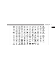
114 UNDERSTANDING THE FEATURES OF YOUR VEHICLE Primary zero one two three four five six seven eight nine star (*) plus (+) pound (#) add location all Voice Commands Alternate(s) Voice Commands Primary Alternate(s) call cancel confirmation prompts continue delete dial download edit emergency English erase all Espanol Francais help home
UNDERSTANDING THE FEATURES OF YOUR VEHICLE 115 Primary language list names list phones mobile mute mute off new entry no pager pair a phone phone pairing phonebook previous record again redial Voice Commands Alternate(s) pairing phone book Voice Commands Primary Alternate(s) return to main menu return or main menu select phone select send set up phone settings or phone set up towing assistance transfer call UConnect威 Tutorial try again voice training work yes 3
116 UNDERSTANDING THE FEATURES OF YOUR VEHICLE General Information This device complies with Part 15 of the FCC rules and RSS 210 of Industry Canada. Operation is subject to the following conditions: • Changes or modifications not expressly approved by the party responsible for compliance could void the user’s authority to operate the equipment. • This device may not cause harmful interference. • This device must accept any interference received, including interference that may cause undesired operation.
UNDERSTANDING THE FEATURES OF YOUR VEHICLE 117 When you press the VR hard-key, you will hear a beep. The beep is your signal to give a command. NOTE: If you do not say a command within a few seconds, the system will present you with a list of options. If you ever wish to interrupt the system while it lists options, press the VR hard-key, listen for the beep, and say your command. Pressing the VR hard-key while the system is speaking is known as “barging in.
118 UNDERSTANDING THE FEATURES OF YOUR VEHICLE Commands The Voice Recognition system understands two types of commands. Universal commands are available at all times. Local commands are available if the supported radio mode is active. Changing the Volume 1. Start a dialogue by pressing the VR hard-key. 2. Say a command (e.g., “Help”). 3. Use the ON/OFF VOLUME rotary knob to adjust the volume to a comfortable level while the Voice Recognition system is speaking.
UNDERSTANDING THE FEATURES OF YOUR VEHICLE 119 Radio FM To switch to the FM band say “FM” or “Radio FM”.
120 UNDERSTANDING THE FEATURES OF YOUR VEHICLE Memo To switch to the voice recorder mode say “Memo”. In this mode, you may say the following commands: • “New Memo” (to record a new memo) — During the recording you may press the VR hard-key to stop recording. You proceed by saying one of the following commands: − “Previous” (to play the previous memo) − “Delete” (to delete a memo) • “Delete All” (to delete all memos) System Setup To switch to system setup say “Setup”.
UNDERSTANDING THE FEATURES OF YOUR VEHICLE 121 Voice Training For users experiencing difficulty with the system recognizing their voice commands or numbers, the UConnect威 system Voice Training feature may be used. 1. Press the VR hard-key, say “System Setup” and once you are in that menu then say “Voice Training.” This will train your own voice to the system and will improve recognition. 2. Repeat the words and phrases when prompted by the UConnect威 System.
122 UNDERSTANDING THE FEATURES OF YOUR VEHICLE Front Seat Adjustment — Recline To adjust the seatback, lift the lever located on the outboard side of the seat, lean back, and release the lever at the desired position. To return the seatback, lift the lever, lean forward, and release the lever. WARNING! • Do not ride with the seatback reclined so that the seat belt is no longer resting against your chest. In a collision you could slide under the seat belt and be seriously or even fatally injured.
UNDERSTANDING THE FEATURES OF YOUR VEHICLE 123 Eight–Way Driver’s Power Seat The driver’s power seat switches are located on the outboard side of the driver’s seat lower side trim. The bottom switch controls up/down, forward/rearward, and tilt adjustment. The top switch controls the seatback recline adjustment. Four–Way Passenger’s Power Seat — If Equipped The front passenger’s power seat switches are located on the outboard side of the passenger seat lower side trim.
124 UNDERSTANDING THE FEATURES OF YOUR VEHICLE Head Restraints Head restraints can reduce the risk of whiplash injury in the event of impact from the rear. Adjustable head restraints should be adjusted so that the upper edge is as high as practical. The head restraints have a locking button which must be pushed in to lower the head restraint to all positions. The restraints may be raised without pushing in the button.
UNDERSTANDING THE FEATURES OF YOUR VEHICLE 125 Front Heated Seats — If Equipped The controls for each heater are located near the bottom center of the instrument panel (below the heater/air conditioning controls). After turning the ignition ON, you can choose from High, Low, or Off heat settings. Amber LEDs on the side of each switch indicate the level of heat in use. Two LEDs are illuminated for High, one for Low, and none for Off. Pressing the switch once will select High-level heating.
126 UNDERSTANDING THE FEATURES OF YOUR VEHICLE WARNING! (Continued) • Do not place anything on the seat that insulates against heat, such as a blanket or cushion. This may cause the seat heater to overheat. To avoid heated seat surfaces coming in contact and potential seat overheating, ALWAYS ensure that the seat heater is in the off position (amber lights indicate High/Low/Off) before placing any of the seats into a folded flat position (if equipped).
UNDERSTANDING THE FEATURES OF YOUR VEHICLE 127 When the High setting is selected, the heater will provide a boosted heat level during the first four minutes of operation. Then, the heat output will drop to the normal High-temperature level. If the High setting is selected, the system will automatically switch to Low after 30 minutes of continuous operation. At that time, the number of illuminated LEDs changes from two to one, indicating the change.
128 UNDERSTANDING THE FEATURES OF YOUR VEHICLE 40/20/40 Second Row Folding Seat Fold and Tumble Second Row Seat The left, center, or right side of the second row seat can be lowered to allow for extended cargo space, and still maintain some rear seating room. In addition, the left and right side of the second row seat can be lowered and tumbled forward to allow access to the third row seat. 1. Pull up on the seatback lever located on the outboard side of the seat.
UNDERSTANDING THE FEATURES OF YOUR VEHICLE 129 WARNING! Do not drive the vehicle with the outer second row seats in the tumbled position. The outer second row seats are only intended to be tumbled for entry and exit to the third row seat. Failure to follow these instructions could result in personal injury.
130 UNDERSTANDING THE FEATURES OF YOUR VEHICLE NOTE: If sitting in the third row seat, pull rearward on the release strap located at the rear of the seat and tumble the seat forward. Release Strap Folding Middle Seatback (Second Row Seat) 1. Pull the release strap.
UNDERSTANDING THE FEATURES OF YOUR VEHICLE 131 2. Lower the center seatback. Center Seat Armrest (Second Row Seat) — If Equipped The second row center seat may be equipped with a armrest. Pull strap to lower armrest.
132 UNDERSTANDING THE FEATURES OF YOUR VEHICLE 50/50 Third Row Folding Seat — If Equipped To Lower Rear Seat Either side of the third row seat can be lowered to allow for extended cargo space, and still maintain some rear seating room. 1. Open the tailgate. 2. Push the seatback release handle (toward rear of vehicle), and lower the seatback using the pull strap. Seatback Release Handle 3. Close the tailgate.
UNDERSTANDING THE FEATURES OF YOUR VEHICLE 133 3. Close the tailgate. To Raise Rear Seat 1. Open the tailgate. WARNING! 2. Detach pull strap from back of seat, and pull seatback upward until it locks into place. Reattach strap. Pull Strap The cargo area in the rear of the vehicle (with the rear seatbacks in the locked-up or folded down position) should not be used as a play area by children when the vehicle is in motion. They could be seriously injured in an accident.
134 UNDERSTANDING THE FEATURES OF YOUR VEHICLE DRIVER MEMORY SEAT — IF EQUIPPED Once programmed, the memory buttons 1 and 2 on the driver’s door panel can be used to recall the driver’s seat, driver’s outside mirror, adjustable brake and accelerator pedals, and radio station preset settings. Your Remote Keyless Entry (RKE) transmitters can also be programmed to recall the same positions when the UNLOCK button is pressed. Driver Memory Switches Your vehicle is equipped with two RKE transmitters.
UNDERSTANDING THE FEATURES OF YOUR VEHICLE 135 Setting Memory Positions and Linking Remote Keyless Entry (RKE) Transmitter to Memory 5. Turn on the radio and set the radio station presets (up to 12 AM and 12 FM stations can be set). NOTE: Each time the S (SET) button and a numbered button 1 or 2 are pressed, you erase the memory settings for that button and store a new one. 6. Turn the ignition switch to the LOCK position and remove the key. 1.
136 UNDERSTANDING THE FEATURES OF YOUR VEHICLE 11. Select ⬙Remote Linked to Memory⬙ in the Electronic Vehicle Information Center (EVIC) and enter ⬙Yes⬙. Refer to “Electronic Vehicle Information Center (EVIC) — Customer-Programmable Features” in Section 4 for more information. 12. Repeat the above steps to set the next memory position, using the other numbered memory button, or to link another RKE transmitter to memory. Memory Position Recall NOTE: The vehicle must be in PARK to recall memory positions.
UNDERSTANDING THE FEATURES OF YOUR VEHICLE 137 To Disable A RKE Transmitter Linked to Memory 1. Turn the ignition switch to the LOCK position, and remove the key. 2. Press and release memory button number 1. The system will recall any memory settings stored in position 1. Wait for the system to complete the memory recall before continuing to Step 3. 3. Press and release the memory S (SET) button located on the driver’s door. 4. Within five seconds, press and release memory button 1 on the driver’s door.
138 UNDERSTANDING THE FEATURES OF YOUR VEHICLE Easy Entry/Exit Seat This feature provides automatic driver’s seat positioning which will enhance driver mobility out of and into the vehicle. There are two possible Easy Entry/Exit adjustments available: • The seat cushion will move rearward approximately 2.5 in (60 mm), if the starting position of the seat is greater than or equal to 2.67 in (68 mm) forward of the rear seat stop when the key is removed from the ignition switch.
UNDERSTANDING THE FEATURES OF YOUR VEHICLE 139 TO OPEN AND CLOSE THE HOOD To open the hood, two latches must be released. 1. Pull the release lever inside your vehicle located below the instrument panel and in front of the driver’s door. 2. Reach under the hood, move safety latch to the left, and lift the hood. To prevent possible damage, do not slam the hood to close it. Use a firm downward push at the center of the hood to ensure that both latches engage.
140 UNDERSTANDING THE FEATURES OF YOUR VEHICLE WARNING! If the hood is not fully latched, it could fly up when the vehicle is moving and block your forward vision. Be sure all hood latches are fully latched before driving. Headlights and Parking Lights Turn the end of the multifunction lever to the first detent for parking light operation. Turn to the second detent for headlight operation. Turn to the third detent for AUTO headlight operation (if equipped).
UNDERSTANDING THE FEATURES OF YOUR VEHICLE 141 Automatic Headlight System — If Equipped Turn the end of the multifunction lever to the third detent, or AUTO position, to activate the automatic headlight system. This system performs two functions. With the engine running and the multifunction lever in the AUTO position, the headlights will turn on and off based on the surrounding light levels.
142 UNDERSTANDING THE FEATURES OF YOUR VEHICLE NOTE: If the windshield or SmartBeam mirror is replaced, the SmartBeam mirror must be re-aimed to ensure proper performance. See your local authorized dealer. To Activate 1. Select “Auto Headlamp Low/High Beams? — Low/ High Beam.” Refer to “Electronic Vehicle Information Center (EVIC) — Customer Programmable Features” in Section 4 of this manual. 2. Turn the end of the multifunction lever to the AUTO headlight position. 3.
UNDERSTANDING THE FEATURES OF YOUR VEHICLE 143 Daytime Running Lights — If Equipped The high beam headlights come on at a low intensity level whenever the engine is running, and the transmission is not in the PARK position. The lights remain on until the ignition switch is turned OFF or the parking brake is engaged. The headlight switch must be used for normal night time driving. Fog Lights — If Equipped The fog light switch is located in the multifunction lever.
144 UNDERSTANDING THE FEATURES OF YOUR VEHICLE • A front fog light is a lighting device providing illumination forward of the vehicle under conditions of fog, rain, snow, or dust. Principally, the front fog light supplements the lower beam of a standard headlight system. even when the doors and liftgate are open. While in the “Off” position the instrument panel lighting is at the lowest light level and may not be suitable for night driving.
UNDERSTANDING THE FEATURES OF YOUR VEHICLE 145 Battery Saver Feature — Exterior/Interior Lights If the multifunction lever is left in the interior light position, parking light position, or the headlight position when the ignition switch is moved to the OFF position, the battery saver feature will automatically turn off the exterior and interior lights after eight minutes. Normal operation will resume when the ignition is turned ON or when the headlight switch is turned to another position.
146 UNDERSTANDING THE FEATURES OF YOUR VEHICLE High Beam Switch Push the multifunction lever away from you to switch the headlights to high beam. Pull the lever towards you to switch the headlights back to low beam. Flash-To-Pass You can signal another vehicle with your headlights by lightly pulling the multifunction lever toward the steering wheel. This will cause the headlights to turn on at high beam and remain on until the lever is released.
UNDERSTANDING THE FEATURES OF YOUR VEHICLE 147 Interior Lights The interior lighting consists of courtesy lights mounted below the instrument panel, reading lights located above the front and rear doors, and a rear cargo light. Opening a door or turning the center of the multifunction lever to the extreme up position will activate all interior courtesy lights. 3 Courtesy/Reading Lights Each light can be turned on by pressing the recessed area of the lens.
148 UNDERSTANDING THE FEATURES OF YOUR VEHICLE WINDSHIELD WIPERS AND WASHERS The front and rear wipers and washers are operated by a switch in the right side control lever. Turn the end of the control lever to select Low, High, or one of the five speed sensitive intermittent windshield wiper speeds. Refer to “Speed Sensitive Intermittent Wiper System” in this section. For information on the rear wiper and washer refer to “Rear Window Features” in this section.
UNDERSTANDING THE FEATURES OF YOUR VEHICLE 149 To use the washer, pull the lever toward you and hold while spray is desired. If the lever is pulled while in the delay range, the wiper will operate for several seconds after the lever is released, and then resume the intermittent interval previously selected. If the lever is pulled while in the off position, the wipers will operate for several wipe cycles, then turn off. WARNING! Sudden loss of visibility through the windshield could lead to an accident.
150 UNDERSTANDING THE FEATURES OF YOUR VEHICLE Rain Sensing Wipers — If Equipped This feature senses moisture on the windshield and automatically activates the wipers for the driver. The feature is especially useful for road splash or overspray from the windshield washers of the vehicle ahead. Rotate the end of the multifunction lever to one of five settings to activate this feature. The sensitivity of the system can be adjusted with the multifunction lever.
UNDERSTANDING THE FEATURES OF YOUR VEHICLE 151 • Transmission in NEUTRAL Position — When the ignition is ON, and the transmission is in the NEUTRAL position, the rain sensing system will not operate until the wiper switch is moved, vehicle speed is greater than 5 mph (8 km/h), or the shift lever is moved out of the NEUTRAL position. TILT/TELESCOPING STEERING COLUMN This feature allows you to tilt the steering column upward or downward. It also allows you to lengthen or shorten the steering column.
152 UNDERSTANDING THE FEATURES OF YOUR VEHICLE the steering wheel outward or push it inward as desired. To lock the steering column in position, push the control handle upward until fully engaged. The position of the brake and accelerator pedals can be adjusted without compromising safety or comfort in actuating the pedals. WARNING! Do not adjust the steering wheel while driving. The telescoping adjustment must be locked while driving.
UNDERSTANDING THE FEATURES OF YOUR VEHICLE 153 Press the top of the switch to move the pedals rearward (toward the driver). • The pedals can be adjusted with the ignition OFF. • The pedals can be adjusted while driving. • The pedals cannot be adjusted when the vehicle is in REVERSE (R) or when the Electronic Speed Control is ON.
154 UNDERSTANDING THE FEATURES OF YOUR VEHICLE The Electronic Speed Control lever is located on the right side of the steering wheel. button a second time. The Cruise Indicator Light will turn off. The Electronic Speed Control system should be turned OFF when not in use. WARNING! Leaving the Electronic Speed Control system on when not in use is dangerous. You could accidentally set the Electronic Speed Control or cause it to go faster than you want. You could lose control and have an accident.
UNDERSTANDING THE FEATURES OF YOUR VEHICLE 155 NOTE: The vehicle should be traveling at a steady speed and on level ground before pressing the SET lever. Release the Electronic Speed Control lever when the desired speed is reached, and the new speed will be set. To Deactivate A soft tap on the brake pedal, pulling the Electronic Speed Control lever towards you, or normal brake pressure while slowing the vehicle will deactivate Electronic Speed Control without erasing the set speed memory.
156 UNDERSTANDING THE FEATURES OF YOUR VEHICLE NOTE: The Electronic Speed Control System has been designed to shut down if multiple Electronic Speed Control switch functions are operated simultaneously in order to ensure proper operation. If this occurs, the system can be reactivated by pushing the Electronic Speed Control switch ON/OFF button and resetting the desired vehicle SET speed. To Accelerate For Passing Depress the accelerator as you would normally.
UNDERSTANDING THE FEATURES OF YOUR VEHICLE 157 active again if the vehicle speed is decreased to speeds less than approximately 10 mph (16 km/h). Rear Park Assist Sensors The four Rear Park Assist Sensors, located in the rear fascia, monitor the area behind the vehicle that is within the sensors’ field of view.
158 UNDERSTANDING THE FEATURES OF YOUR VEHICLE The system dimly illuminates the two outer most yellow LEDs when it is ON and detecting no obstacles. The following chart shows the warning display operation when the system is detecting an obstacle: WARNING DISPLAY DISTANCES DISPLAY LED 1st LED 2nd LED 3rd LED 4th LED 5th LED 6th LED 7th LED 8th LED OBSTACLE DISTANCE FROM: REAR CORNERS REAR CENTER 59 in (150 cm) 51 in (130 cm) 45 in (115 cm) 31.5 in (80 cm) 39 in (100 cm) 25.5 in (65 cm) 33.
UNDERSTANDING THE FEATURES OF YOUR VEHICLE 159 Enable/Disable The Rear Park Assist System The Rear Park Assist System can be enabled and disabled with a switch located on the upper switch bank of the instrument panel. When the switch is pressed to disable the system, the instrument cluster will display the “PARK ASSIST DISABLED” message. Refer to “Electronic Vehicle Information Center (EVIC)” in Section 4 of this manual.
160 UNDERSTANDING THE FEATURES OF YOUR VEHICLE Cleaning The Rear Park Assist System Clean the Rear Park Assist Sensors with water, car wash soap and a soft cloth. Do not use rough or hard cloths. Do not scratch or poke the sensors. Otherwise, you could damage the sensors.
UNDERSTANDING THE FEATURES OF YOUR VEHICLE 161 4. When the vehicle is shifted into REVERSE, an image of the rear of the vehicle will appear with a caution note to ⬙check entire surroundings⬙ displayed across the top of the screen. After five seconds this note will disappear. 5. When the vehicle is shifted out of REVERSE, the rear camera mode is exited and the navigation or audio screen appears again. CAUTION! • To avoid vehicle damage, the Rear Camera system should only be used as a parking aid.
162 UNDERSTANDING THE FEATURES OF YOUR VEHICLE OVERHEAD CONSOLE — IF EQUIPPED The overhead console contains an optional universal garage door opener (HomeLink威), storage for sunglasses, and optional power sunroof switches. GARAGE DOOR OPENER — IF EQUIPPED HomeLink威 replaces up to three remote controls (handheld transmitters) that operate devices such as garage door openers, motorized gates, lighting, or home security systems. The HomeLink威 unit operates off your vehicle’s battery.
UNDERSTANDING THE FEATURES OF YOUR VEHICLE 163 WARNING! HomeLink威 Buttons NOTE: HomeLink威 is disabled when the Vehicle Security Alarm is active. • Your motorized door or gate will open and close while you are training the Universal Transceiver. Do not train the transceiver if people or pets are in the path of the door or gate. Only use this transceiver with a garage door opener that has a “stop and reverse” feature as required by federal safety standards.
164 UNDERSTANDING THE FEATURES OF YOUR VEHICLE Programming HomeLink姞 Before You Begin If you have not trained any of the HomeLink威 buttons, erase all channels before you begin training. To do this, press and hold the two outside buttons for up to 20 seconds. The EVIC will display “CLEARING CHANNELS.” Release the buttons when the EVIC message states “CHANNELS CLEARED.
UNDERSTANDING THE FEATURES OF YOUR VEHICLE 165 NOTE: Some gate operators and garage door openers may require you to replace Step 3 with procedures noted in the “Gate Operator/Canadian Programming” section. 4. Press and hold the just-trained HomeLink威 button. If the channel has been trained, the EVIC display will now state “CHANNEL # TRANSMIT.
166 UNDERSTANDING THE FEATURES OF YOUR VEHICLE 6. Firmly press and release the “learn” or “training” button. The name and color of the button may vary by manufacturer. NOTE: There are 30 seconds in which to initiate the next step after the “Learn” button has been pressed. 7. Return to the vehicle and press the programmed HomeLink威 button twice (holding the button for two seconds each time). If the device is plugged in and activates, programming is complete.
UNDERSTANDING THE FEATURES OF YOUR VEHICLE 167 If you unplugged the device for training, plug it back in at this time. Then proceed with Step 4 under “Programming HomeLink威” earlier in this section. Using HomeLink姞 To operate, simply press and release the programmed HomeLink威 button. Activation will now occur for the trained device (i.e., garage door opener, gate operator, security system, entry door lock, home/office lighting, etc.) The hand-held transmitter of the device may also be used at any time.
168 UNDERSTANDING THE FEATURES OF YOUR VEHICLE Troubleshooting Tips If you are having trouble programming HomeLink威, here are some of the most common solutions: 2. This device must accept any interference that may be received including interference that may cause undesired operation • Replace the battery in the original transmitter. NOTE: The transmitter has been tested and it complies with FCC and IC rules.
UNDERSTANDING THE FEATURES OF YOUR VEHICLE 169 POWER SUNROOF — IF EQUIPPED The power sunroof switch is located on the overhead console. Power Sunroof Switch WARNING! • Never leave children in a vehicle with the keys in the ignition switch. Occupants, particularly unattended children, can become entrapped by the power sunroof while operating the power sunroof switch. Such entrapment may result in serious injury or death.
170 UNDERSTANDING THE FEATURES OF YOUR VEHICLE Opening Sunroof - Express Press the switch rearward and release, and the sunroof will open automatically from any position. The sunroof will open fully, then stop automatically. This is called Express Open. During Express Open operation, any movement of the sunroof switch will stop the sunroof. Closing Sunroof - Express Press the switch forward and release, and the sunroof will close automatically from any position.
UNDERSTANDING THE FEATURES OF YOUR VEHICLE 171 Sunshade Operation The sunshade can be opened manually. However, the sunshade will open automatically as the sunroof opens. Sunroof Maintenance Use only a non-abrasive cleaner and a soft cloth to clean the glass panel. NOTE: The sunshade cannot be closed if the sunroof is open. Ignition Off Operation The power sunroof switches remain active for 10 minutes after the ignition switch has been turned off. Opening either front door will cancel this feature.
172 UNDERSTANDING THE FEATURES OF YOUR VEHICLE COMMAND-VIEW™ SKYLIGHTS — IF EQUIPPED The two fixed skylights are above the second row seats. The glass is tinted to shield the second row occupants from the sun and glare. Each skylight includes a roller shade that is concealed in the assembly to block out more light when desired. NOTE: Hold onto shade handle until shade is completely open or closed.
UNDERSTANDING THE FEATURES OF YOUR VEHICLE 173 POWER OUTLETS Front Power Outlet To the left and right of the convenience tray (lower center of instrument panel) is a power outlet for accessories. Pull lightly on the tab of the plastic cover to access the outlet. 3 Rear Power Outlet — If Equipped The rear power outlet (if equipped) is located in the left rear cargo area.
174 UNDERSTANDING THE FEATURES OF YOUR VEHICLE WARNING! CAUTION! To avoid serious injury or death: • Do not use a three-prong adapter. • Do not insert any objects into the receptacles. • Do not touch with wet hands. • Close the lid when not in use and while driving the vehicle. • If this outlet is mishandled, it may cause an electric shock and failure. • Many accessories that can be plugged in draw power from the vehicle’s battery, even when not in use (i.e., cellular phones, etc.).
UNDERSTANDING THE FEATURES OF YOUR VEHICLE 175 POWER INVERTER — IF EQUIPPED There is a 115–Volt, 150–Watt inverter outlet located on the back of the center console to convert DC current to AC current. This outlet can be used to power small appliances and electronics. Press the power inverter switch (located on the upper switch bank) to turn the power on to the outlet. Press the switch again to turn the power off.
176 UNDERSTANDING THE FEATURES OF YOUR VEHICLE NOTE: When the power inverter switch is pressed, there will be a delay of approximately one second before the inverter status indicator turns ON. The status indicator of the AC power inverter indicates whether the inverter is producing AC power. CUPHOLDERS Front Cupholders In the center console, there are two cupholders for the front seat passengers. NOTE: Due to built-in overload protection, the inverter will shut down if the power rating is exceeded.
UNDERSTANDING THE FEATURES OF YOUR VEHICLE 177 NOTE: The cupholder insert is removable, from the console, for cleaning. It can be reinstalled with the larger cup depression towards the passenger seat, but the top surface will not be flush with the console surface. Cupholders (Second Row Seat) The second row seat has two cupholders in the center armrest. Lower the center armrest. Refer to “Seats” in this section. Press the front of the cupholder, and the cupholder will come out of the armrest.
178 UNDERSTANDING THE FEATURES OF YOUR VEHICLE Cupholders (Third Row Seat) The third row seat passengers have cupholders on the left and right rear trim panels. CARGO AREA FEATURES Cargo Load Floor The panel in the load floor is reversible for added utility. One side is carpeted and the other side features a plastic lined tray which holds a variety of items.
UNDERSTANDING THE FEATURES OF YOUR VEHICLE 179 The cargo load floor is held by spring loaded latches. In order to use the cargo load floor, use the following procedure: 1. Flip up pull loop(s) so they are perpendicular (straight up) to the top surface of the tray. 2. Pull up on loop(s) and twist 90 degrees, so they are parallel to the slotted hole in tray. 3. Lift tray over loop(s), and reposition tray. Rear Storage Cover NOTE: The cargo load floor latches should not be used as cargo tie-downs.
180 UNDERSTANDING THE FEATURES OF YOUR VEHICLE 4. Pull up on loop(s) and twist 90 degrees, so they are perpendicular (straight up) to the slotted hole in tray. 5. Push loop(s) back down, so they are parallel to the top of the tray. REAR WINDOW FEATURES Rear Window Wiper/Washer A switch on the right side of the steering column controls operation of the rear wiper/washer function. Rotating the center of the switch forward to the on position will activate the wiper.
UNDERSTANDING THE FEATURES OF YOUR VEHICLE 181 If the liftgate flipper glass is open, connection to the rear window wiper is interrupted preventing activation of the rear wiper blade. When the liftgate flipper glass is closed, the rear wiper switch or the ignition switch needs to be turned off and on to restart the rear wiper. Rear Window Defroster — If Equipped Press this button (located on the climate control panel) to turn on the rear window defroster and the heated side mirrors (if equipped).
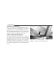
182 UNDERSTANDING THE FEATURES OF YOUR VEHICLE rack system or a number of aftermarket rails that are tailored to your life style or activities. The optional cross rails have five specific locations identified by a feature on both the side rail and the cross rail. Cross rails must be secured in one of the five detent locations on the side rail to prevent movement with a sudden stop.
UNDERSTANDING THE FEATURES OF YOUR VEHICLE 183 CAUTION! CAUTION! (Continued) • To prevent damage to the roof of your vehicle, DO NOT carry any loads on the roof rack without cross rails installed. The load should be secured and placed on top of the cross rails, not directly on the roof. If it is necessary to place the load on the roof, place a blanket or some other protection between the load and the roof surface.
UNDERSTANDING YOUR INSTRUMENT PANEL CONTENTS 䡵 Instrument Panel Features . . . . . . . . . . . . . . . . 189 ▫ Compass Display . . . . . . . . . . . . . . . . . . . . . 210 䡵 Instrument Cluster . . . . . . . . . . . . . . . . . . . . . 190 ▫ Personal Settings (Customer-Programmable Features) . . . . . . . . . . . . . . . . . . . . . . . . . . . 212 䡵 Instrument Cluster Description . . . . . . . . . . . . 191 䡵 Electronic Vehicle Information Center (EVIC) . .
186 UNDERSTANDING YOUR INSTRUMENT PANEL ▫ Notes On Playing MP3/WMA Files . . . . . . . . 229 ▫ Operating Instructions — Radio Mode . . . . . . 237 ▫ List Button (Disc Mode For MP3/WMA Play). . . . . . . . . . . . . . . . . . . . . 231 ▫ Operation Instructions — CD Mode For CD And MP3 Audio Play . . . . . . . . . . . . . . . . . . 240 ▫ Info Button (Disc Mode For MP3/WMA Play) . . . . . . . . . . . . . . . . . . . . . . . . . . . . . 231 ▫ Notes On Playing MP3 Files . . . . . . . . . . . . .
UNDERSTANDING YOUR INSTRUMENT PANEL 187 䡵 Universal Consumer Interface (UCI) — If Equipped. . . . . . . . . . . . . . . . . . . . . . . . . . . 257 ▫ Connecting The iPod威 . . . . . . . . . . . . . . . . . 258 ▫ Reception Quality . . . . . . . . . . . . . . . . . . . . 264 ▫ Operating Instructions - Satellite Mode . . . . . 264 ▫ Using This Feature . . . . . . . . . . . . . . . . . . . 258 ▫ Operating Instructions - Hands-Free Phone (If Equipped) . . . . . . . . . . . . . . . . . . . . . . . .
188 UNDERSTANDING YOUR INSTRUMENT PANEL 䡵 Climate Controls . . . . . . . . . . . . . . . . . . . . . . 271 ▫ Rear Climate Control — If Equipped . . . . . . . 281 ▫ Manual Air Conditioning And Heating System — If Equipped . . . . . . . . . . . . . . . . . 271 ▫ Operating Tips . . . . . . . . . . . . . . . . . . . . . . 283 ▫ Automatic Temperature Control — If Equipped . . . . . . . . . . . . . . . . . . . . . . . . . . 274 ▫ Operating Tips Chart . . . . . . . . . . . . . . . . . .
UNDERSTANDING YOUR INSTRUMENT PANEL 189 INSTRUMENT PANEL FEATURES 4 1 2 3 4 - Air Outlet - Instrument Cluster - Radio - Glove Compartment 5 6 7 8 - Upper Switch Bank Power Outlet/Cigar Lighter Storage Bin Power Outlet 9 - Lower Switch Bank 10 - Climate Controls 11 - Ignition Switch 12 - Storage Bin
190 UNDERSTANDING YOUR INSTRUMENT PANEL INSTRUMENT CLUSTER
UNDERSTANDING YOUR INSTRUMENT PANEL 191 INSTRUMENT CLUSTER DESCRIPTION 1. Speedometer Indicates vehicle speed. 2. Brake Warning Light This light monitors various brake functions, including brake fluid level and parking brake application. If the brake light turns on, it may indicate that the parking brake is applied, that the brake fluid level is low, or that there is a problem with the anti-lock brake system reservoir.
192 UNDERSTANDING YOUR INSTRUMENT PANEL WARNING! Driving a vehicle with the red brake light on is dangerous. Part of the brake system may have failed. It will take longer to stop the vehicle. You could have an accident. Have the vehicle checked immediately. Vehicles equipped with the Anti-Lock Brake System (ABS), are also equipped with Electronic Brake Force Distribution (EBD). In the event of an EBD failure, the Brake Warning Light will turn on along with the ABS Light.
UNDERSTANDING YOUR INSTRUMENT PANEL 193 5. Malfunction Indicator Light (MIL) The Malfunction Indicator Light (MIL) is part of an onboard diagnostic system called OBD II that monitors engine and automatic transmission control systems. The light will illuminate when the key is in the ON position before engine start. If the bulb does not come on when turning the key from OFF to ON, have the condition checked promptly. Certain conditions such as a loose or missing gas cap, poor fuel quality, etc.
194 UNDERSTANDING YOUR INSTRUMENT PANEL If the ABS light is on, the brake system should be serviced as soon as possible to restore the benefits of Anti-Lock brakes. If the ABS light does not turn on when the Ignition switch is turned to the ON position, have the light inspected by an authorized dealer. 8. Tachometer Indicates the engine speed in revolutions per minute (RPM). 9. Vehicle Security Light This light will flash rapidly for approximately 15 seconds when the vehicle theft alarm is arming.
UNDERSTANDING YOUR INSTRUMENT PANEL 195 12. Tire Pressure Monitoring Telltale Light Each tire, including the spare (if provided), should be checked monthly, when cold and inflated to the inflation pressure recommended by the vehicle manufacturer on the vehicle placard or tire inflation pressure label. (If your vehicle has tires of a different size than the size indicated on the vehicle placard or tire inflation pressure label, you should determine the proper tire inflation pressure for those tires.
196 UNDERSTANDING YOUR INSTRUMENT PANEL alternate tires or wheels on the vehicle that prevent the TPMS from functioning properly. Always check the TPMS malfunction telltale after replacing one or more tires or wheels on your vehicle, to ensure that the replacement or alternate tires and wheels allow the TPMS to continue to function properly. CAUTION! The TPMS has been optimized for the original equipment tires and wheels.
UNDERSTANDING YOUR INSTRUMENT PANEL 197 WARNING! A hot engine cooling system is dangerous. You or others could be badly burned by steam or boiling coolant. You may want to call an authorized dealership for service if your vehicle overheats. If you decide to look under the hood yourself, see Section 7 of this manual. Follow the warnings under the Cooling System Pressure Cap paragraph. 14.
198 UNDERSTANDING YOUR INSTRUMENT PANEL 17. 4WD LOW Mode Indicator — If Equipped This light alerts the driver that the vehicle is in the 4WD LOW mode. The front and rear driveshafts are mechanically locked together forcing the front and rear wheels to rotate at the same speed. 18. Seat Belt Warning Light When the ignition switch is first turned ON, this light will turn on for five to eight seconds as a bulb check. During the bulb check, if the driver’s seat belt is unbuckled, a chime will sound.
UNDERSTANDING YOUR INSTRUMENT PANEL 199 NOTE: You must apply the brakes before shifting from PARK. 22. Fuel Gauge The pointer shows the level of fuel in the fuel tank when the ignition switch is in the ON position. 23. Electronic Throttle Control (ETC) Warning Light This light informs you of a problem with the Electronic Throttle Control (ETC) system. If a problem is detected, the light will come on while the engine is running.
200 UNDERSTANDING YOUR INSTRUMENT PANEL 26. Low Fuel Light When the fuel level reaches approximately 2.3 U.S. Gallons (8.7 Liters) this light will come on and remain on until fuel is added. The Low Fuel Warning Light may turn on and off again, especially during and after hard braking, accelerations, or turns. This occurs due to the shifting of the fuel in the tank. Also, a single chime will sound.
UNDERSTANDING YOUR INSTRUMENT PANEL 201 • Outside Temperature Display • Trip Computer Functions The system allows the driver to select information by pressing the following buttons mounted on the steering wheel: MENU Button Press and release the MENU button and the mode displayed will change between Trip Functions, Personal Settings, and System Status. FUNCTION SELECT Button Press the FUNCTION SELECT button to select the displayed function YES (Y) or NO (N).
202 UNDERSTANDING YOUR INSTRUMENT PANEL • DAMAGED KEY — KEY DOES NOT COMMUNICATE • KEY NOT PROGRAMMED — KEY NOT PROGRAMMED • WRONG KEY — KEY DOES NOT BELONG TO VEHICLE • KEY NOT PROGRAMMED — EXCEEDED KEY PROGRAM LIMIT • PROGRAMMING ACTIVE — NEW KEY PROGRAMMED • SERVICE SECURITY KEY • DRIVER/PASSENGER DOOR OPEN (with graphic) • LEFT/RIGHT REAR DOOR OPEN (with graphic) • X DOORS OPEN (with graphic) • LIFTGATE OPEN (with graphic) • LIFTGATE/DOOR OPEN (with graphic) • LIFTGATE/DOORS OPEN (with graphic) • LIFT
UNDERSTANDING YOUR INSTRUMENT PANEL 203 • LIFTGLASS/HOOD OPEN (with graphic) • SERVICE 4WD SYSTEM • WASHER FLUID LOW (with graphic) • 4WD SYSTEM IN NEUTRAL • COOLANT LOW (with graphic) • LOW BRAKE FLUID LEVEL • OIL CHANGE REQUIRED • WARNING! LIMIT SPEED • OIL CHANGE RESET • CHECK GASCAP • CHECK GAUGES • ESP OFF • AUTO HIGH BEAMS ON • IOD FUSE OUT • AUTO HIGH BEAMS OFF • HILL DESCENT CONTROL • PARK ASSIST DISABLED • MEMORY #1 POSITIONS SET • SERVICE SUSPENSION • MEMORY #2 POSITIONS SET •
204 UNDERSTANDING YOUR INSTRUMENT PANEL • DRIVER 1 MEMORY • DRIVER 2 MEMORY • ADJ. PEDALS DISABLED — CRUISE CONTROL SET • ADJ.
UNDERSTANDING YOUR INSTRUMENT PANEL 205 • IGNITION POSITION • PRESS BRAKE TO START • PUSH BUTTON OR INSERT KEY • TURN TO ON • ECO – Multi-Displacement System (MDS) is activated (if equipped with MDS) Engine Oil Change Indicator System Oil Change Required Your vehicle is equipped with an engine oil change indicator system. The “Oil Change Required” message will flash in the EVIC display for approximately 10 seconds after a single chime has sounded to indicate the next scheduled oil change interval.
206 UNDERSTANDING YOUR INSTRUMENT PANEL Trip Functions Press and release the MENU button until one of the following Trip Functions displays in the EVIC: • Average Fuel Economy/Fuel Saver Mode (5.7L Engine Only) • Distance To Empty • Trip A • Trip B • Elapsed Time • Service Distance • Display Units of Measure In Press the SCROLL button to cycle through all the Trip Computer functions. The Trip Functions mode displays the following information: Average Fuel Economy / Fuel Saver Mode (5.
UNDERSTANDING YOUR INSTRUMENT PANEL 207 4 4-Cylinder Operation - MDS On This feature allows you to monitor when the MDS switches off the fuel on four of the eight cylinders and it can be used to modify driving habits in order to increase the time in which the fuel saver mode is active.
208 UNDERSTANDING YOUR INSTRUMENT PANEL Distance To Empty (DTE) Shows the estimated distance that can be traveled with the fuel remaining in the tank. This estimated distance is determined by a weighted average of the instantaneous and average fuel economy, according to the current fuel tank level. DTE cannot be reset through the FUNCTION SELECT button.
UNDERSTANDING YOUR INSTRUMENT PANEL 209 To Reset The Display Reset will only occur while a resettable function is being displayed. Press and release the FUNCTION SELECT button once to clear the resettable function being displayed. To reset all resettable functions, press and release the FUNCTION SELECT button a second time within three seconds of resetting the currently displayed function (>Reset ALL will display during this three second window).
210 UNDERSTANDING YOUR INSTRUMENT PANEL NOTE: Under certain conditions, the display may be superseded by another display of higher priority. But when the ignition state is changed, the display always re-appears. Compass Display The compass readings indicate the direction the vehicle is facing. Press and release the COMPASS/TEMPERATURE button to display one of eight compass readings and the outside temperature.
UNDERSTANDING YOUR INSTRUMENT PANEL 211 5. Complete one or more 360–degree turns (in an area free from large metal or metallic objects) until the “CAL” indicator turns off. The compass will now function normally. Compass Variance Compass Variance is the difference between Magnetic North and Geographic North. To compensate for the differences, the variance should be set for the zone where the vehicle is driven, per the zone map.
212 UNDERSTANDING YOUR INSTRUMENT PANEL 4. Press and release the FUNCTION SELECT button until the proper variance zone is selected according to the map. 5. Press and release the COMPASS/TEMPERATURE button to exit. Personal Settings (Customer-Programmable Features) Personal Settings allows the driver to set and recall features when the transmission is in PARK. Press and release the MENU button until Personal Settings displays in the EVIC.
UNDERSTANDING YOUR INSTRUMENT PANEL 213 make your selection, press and release the FUNCTION SELECT button until YES (Y) or NO (N) appears. Remote Key Unlock When “Driver Door 1st Press” is selected, only the driver’s door will unlock on the first press of the Remote Keyless Entry (RKE) transmitter UNLOCK button. When “Driver Door 1st Press” is selected, you must press the RKE transmitter UNLOCK button twice to unlock the passenger’s doors.
214 UNDERSTANDING YOUR INSTRUMENT PANEL Headlamp Off Delay When this feature is selected, the driver can choose to have the headlights remain on for 0, 30, 60, or 90 seconds when exiting the vehicle. To make your selection, press and release the FUNCTION SELECT button until “0,” “30,” “60,” or “90” appears. Automatic High Beams (Available with SmartBeam Only) When this feature is selected, the high beam headlights will deactivate automatically under certain conditions.
UNDERSTANDING YOUR INSTRUMENT PANEL 215 Easy Entry/Exit Seat (Available with Memory Seat Only) This feature provides automatic driver seat positioning to enhance driver mobility when entering and exiting the vehicle. To make your selection, press and release the FUNCTION SELECT button until YES (Y) or NO (N) appears. NOTE: The seat will return to the memorized seat location (if Recall Memory with Remote Key Unlock is set to ON) when the RKE transmitter is used to unlock the door.
216 UNDERSTANDING YOUR INSTRUMENT PANEL Display Units of Measure In The EVIC, odometer, and navigation system (if equipped) can be changed between English and Metric units of measure. To make your selection, press and release the FUNCTION SELECT button until “US or “METRIC” appears.
UNDERSTANDING YOUR INSTRUMENT PANEL 217 • Tire Pressure Monitor System (Shows the current pressure of all four road tires.) For additional information, refer to “Tire Pressure Monitor System” in Section 5 of this manual. NOTE: • Tires heat up during normal driving conditions. Heat will cause the tire pressure to increase from 2 to 6 psi (14 to 41 kPa) during normal driving conditions. Refer to “Tire Inflation Pressures” in Section 5 for additional information.
218 UNDERSTANDING YOUR INSTRUMENT PANEL SALES CODE REQ — AM/FM STEREO RADIO AND 6–DISC CD/DVD CHANGER (MP3/WMA AUX JACK) NOTE: The radio sales code is located on the lower right side of the radio faceplate. Operating Instructions - Radio Mode NOTE: The ignition switch must be in the ON or ACC position to operate the radio. Power Switch/Volume Control (Rotary) Push the ON/VOLUME control knob to turn on the radio. Press the ON/VOLUME control knob a second time to turn off the radio.
UNDERSTANDING YOUR INSTRUMENT PANEL 219 SEEK Buttons Press and release the SEEK buttons to search for the next listenable station in AM/FM mode. Press the right switch to seek up and the left switch to seek down. The radio will remain tuned to the new station until you make another selection. Holding either button will bypass stations without stopping until you release it.
220 UNDERSTANDING YOUR INSTRUMENT PANEL Clock Setting Procedure 1. Press and hold the TIME button until the hours blink. 2. Adjust the hours by turning the right side TUNE/ SCROLL control knob. 3. After adjusting the hours, press the right side TUNE/ SCROLL control knob to set the minutes. The minutes will begin to blink. 4. Adjust the minutes using the right side TUNE/ SCROLL control knob. Press the TUNE/SCROLL control knob to save the time change. 5. To exit, press any button/knob or wait five seconds.
UNDERSTANDING YOUR INSTRUMENT PANEL 221 Setting the Tone, Balance, and Fade Push the rotary TUNE/SCROLL control knob and BASS will display. Turn the TUNE/SCROLL control knob to the right or left to increase or decrease the bass tones. Push the rotary TUNE/SCROLL control knob a fifth time and FADE will display. Turn the TUNE/SCROLL control knob to the left or right to adjust the sound level between the front and rear speakers. Push the rotary TUNE/SCROLL control knob a second time and MID will display.
222 UNDERSTANDING YOUR INSTRUMENT PANEL Toggle the MUSIC TYPE button to select the following format types: Program Type No program type or undefined Adult Hits Classical Classic Rock College Country Foreign Language Information Jazz News Nostalgia Oldies 16-Digit Character Display None Adlt Hit Classicl Cls Rock College Country Language Inform Jazz News Nostalga Oldies Program Type Personality Public Rhythm and Blues Religious Music Religious Talk Rock Soft Soft Rock Soft Rhythm and Blues Sports Talk Top
UNDERSTANDING YOUR INSTRUMENT PANEL 223 By pressing the SEEK button when the Music Type icon is displayed, the radio will be tuned to the next frequency station with the same selected Music Type name. The Music Type function only operates when in the FM mode. If a preset button is activated while in the Music Type (Program Type) mode, the Music Type mode will be exited and the radio will tune to the preset station.
224 UNDERSTANDING YOUR INSTRUMENT PANEL • Angle – Repeatedly pressing SELECT will change the viewing angle if supported by the DVD disc (if equipped). NOTE: • The available selections for each of the above entries varies depending upon the disc. • These selections can only be made while playing a DVD. • VES™ Power - Allows you to turn VES™ ON and OFF (if equipped). • VES™ Lock - Locks out rear VES™ remote controls (if equipped).
UNDERSTANDING YOUR INSTRUMENT PANEL 225 Audio Language — If Equipped Selecting this item allows you to choose a default audio language (effective only if the language is supported by the disc). You can select a language not listed by scrolling down and selecting ⬙other.⬙ Enter the country code using the TUNE/SCROLL control knob to scroll up and down to select the number and then push to select.
226 UNDERSTANDING YOUR INSTRUMENT PANEL NOTE: The user will have to set these defaults before loading a disc. If changes are made to these settings after a disc is loaded, changes will not be effective. Also, the defaults are effective only if the disc supports the customer-preferred settings. AM and FM Buttons Press the buttons to select AM or FM mode. SET Button — To Set the Pushbutton Memory When you are receiving a station that you wish to commit to pushbutton memory, press the SET button.
UNDERSTANDING YOUR INSTRUMENT PANEL 227 Operation Instructions - (DISC MODE for CD and MP3/WMA Audio Play, DVD-VIDEO) The radio DVD player and many DVD discs are coded by geographic region. These region codes must match in order for the disc to play. If the region code for the DVD disc does not match the region code for the radio DVD player, it will not play the disc. Customers may take their vehicle to an authorized dealer to change the region code of the player a maximum of five times.
228 UNDERSTANDING YOUR INSTRUMENT PANEL Eject Button — Ejecting Compact Disc(s) Press the EJECT button and the pushbutton with the corresponding number (1-6) where the CD was loaded and the disc will unload and move to the entrance for easy removal. Radio display will show ⬙EJECTING DISC⬙ when the disc is being ejected and prompt the user to remove the disc. Press and hold the EJECT button for five seconds and all CDs will be ejected from the radio. The disc can be ejected with the radio and ignition OFF.
UNDERSTANDING YOUR INSTRUMENT PANEL 229 Notes On Playing MP3/WMA Files The radio can play MP3/WMA files; however, acceptable MP3/WMA file recording media and formats are limited. When writing MP3/WMA files, pay attention to the following restrictions.
230 UNDERSTANDING YOUR INSTRUMENT PANEL If a disc contains multi-formats, such as CD audio and MP3/WMA tracks, the radio will only play the MP3/ WMA tracks on that disc. MPEG Specification Supported MP3/WMA File Formats The radio will recognize only files with the *.MP3/WMA extension as MP3/WMA files. Non-MP3/WMA files named with the *.MP3/WMA extension may cause playback problems. The radio is designed to recognize the file as an invalid MP3/WMA and will not play the file.
UNDERSTANDING YOUR INSTRUMENT PANEL 231 Playback of MP3/WMA Files When a medium containing MP3/WMA data is loaded, the radio checks all files on the medium. If the medium contains a lot of folders or files, the radio will take more time to start playing the MP3/WMA files.
232 UNDERSTANDING YOUR INSTRUMENT PANEL Press and hold the INFO button again for three seconds to return to ⬙elapsed time⬙ display. SCAN Button (Auxiliary Mode) No function. Operation Instructions - Auxiliary Mode The auxiliary (AUX) jack is an audio input jack which allows the user to plug in a portable device such as an MP3/WMA player, cassette player, or microphone and utilize the vehicle’s audio system to amplify the source and play through the vehicle speakers.
UNDERSTANDING YOUR INSTRUMENT PANEL 233 Operating Instructions — Voice Recognition System (VR) (If Equipped) For the radio, refer to “Voice Recognition System (VR)” in Section 3. Dolby威 Manufactured under license from Dolby威 Laboratories. ⬙Dolby威⬙ and the double-D symbol are trademarks of Dolby威 Laboratories. For UConnect威 “Voice Recognition System (VR),” refer to “Hands-Free Communication (UConnect威)” in Section 3.
234 UNDERSTANDING YOUR INSTRUMENT PANEL AM/FM/CD/DVD MULTIMEDIA SYSTEM RADIO (RER/REN) – IF EQUIPPED NOTE: The sales code is located on the lower right side of the unit’s faceplate. The REN and RER Multimedia systems contain a radio, CD/DVD player, USB port, and a 30-gigabyte hard drive (HDD). Sirius Satellite Radio is optional. The 6.5 in (16.5 cm) touch screen allows for easy menu selection. The RER radio also contains a Global Positioning System (GPS)-based Navigation system.
UNDERSTANDING YOUR INSTRUMENT PANEL 235 3. Touch the screen where “User Clock” is displayed. The clock setting menu will appear on the screen. 4. To move the hour forward, touch the screen where the word “Hour” with the arrow pointing upward is displayed. To move the hour backward, touch the screen where the word “Hour” with the arrow pointing downward is displayed. 5. To move the minute forward, touch the screen where the word “Min” with the arrow pointing upward is displayed.
236 UNDERSTANDING YOUR INSTRUMENT PANEL 3. When this feature is on, a check mark will appear in the box next to the words “Show Time if Radio is Off.” Touch the screen where the words “Show Time if Radio is Off” are displayed to change the current setting. SALES CODE RES — AM/FM STEREO RADIO WITH CD PLAYER (MP3 AUX JACK) NOTE: The radio sales code is located on the lower right side of the radio faceplate. Changing the Time Zone 1. Turn on the multimedia system. 2.
UNDERSTANDING YOUR INSTRUMENT PANEL 237 Operating Instructions — Radio Mode NOTE: The ignition switch must be in the ON or ACC position to operate the radio. Power Switch/Volume Control (Rotary) Push the ON/VOLUME control knob to turn on the radio. Push the ON/VOLUME control knob a second time to turn off the radio. Electronic Volume Control The electronic volume control turns continuously (360 degrees) in either direction, without stopping.
238 UNDERSTANDING YOUR INSTRUMENT PANEL 4. Adjust the minutes using the right side TUNE/ SCROLL control knob. Press the TUNE/SCROLL control knob to save time change. 5. To exit, press any button/knob, or wait five seconds. RW/FF Pressing the RW (Rewind) or FF (Fast Forward) buttons causes the tuner to search for the next frequency in the direction of the arrows. This feature operates in either AM or FM frequencies.
UNDERSTANDING YOUR INSTRUMENT PANEL 239 Push the rotary TUNE/SCROLL control knob again to exit setting tone, balance, and fade. AM/FM Button Press the buttons to select either AM or FM mode. SET/RND Button — To Set the Pushbutton Memory When you are receiving a station that you wish to commit to pushbutton memory, press the SET/RND button. The symbol SET 1 will now show in the display window. Select the button (1 to 6) you wish to lock onto this station and press and release that button.
240 UNDERSTANDING YOUR INSTRUMENT PANEL Operation Instructions — CD MODE For CD And MP3 Audio Play NOTE: • The ignition switch must be in the ON or ACC position to operate the radio. • This radio is capable of playing compact discs (CD), recordable compact discs (CD-R), rewritable compact discs (CD-RW), compact discs with MP3 tracks and multisession compact discs with CD and MP3 tracks. Inserting Compact Disc(s) Gently insert one CD into the CD player with the CD label facing up.
UNDERSTANDING YOUR INSTRUMENT PANEL 241 EJECT Button - Ejecting a CD Press the EJECT button to eject the CD. If you have ejected a disc and have not removed it within 10 seconds, it will be reloaded. If the CD is not removed, the radio will reinsert the CD but will not play it. A disc can be ejected with the radio and ignition OFF. NOTE: Ejecting with the ignition OFF is not allowed on convertible or soft-top models (if equipped). SEEK Button Press the right SEEK button for the next selection on the CD.
242 UNDERSTANDING YOUR INSTRUMENT PANEL SET/RND Button (Random Play Button) Press this button while the CD is playing to activate Random Play. This feature plays the selections on the compact disc in random order to provide an interesting change of pace. Press the right SEEK button to move to the next randomly selected track. Press the RND button a second time to stop Random Play. Notes on Playing MP3 Files The radio can play MP3 files; however, acceptable MP3 file recording media and formats are limited.
UNDERSTANDING YOUR INSTRUMENT PANEL 243 • Maximum number of characters in file/folder names: • Level 1: 12 (including a separator ⬙.⬙ and a threecharacter extension) • Level 2: 31 (including a separator ⬙.⬙ and a threecharacter extension) Multisession disc formats are supported by the radio. Multisession discs may contain combinations of normal CD audio tracks and computer files (including MP3 files). Discs created with an option such as ⬙keep disc open after writing⬙ are most likely multisession discs.
244 UNDERSTANDING YOUR INSTRUMENT PANEL ID3 Tag information for artist, song title, and album title are supported for version 1 ID3 tags. ID3 version 2 is not supported by the radios. Playlist files are not supported. MP3 Pro files are not supported. Playback of MP3 Files When a medium containing MP3 data is loaded, the radio checks all files on the medium. If the medium contains a lot of folders or files, the radio will take more time to start playing the MP3 files.
UNDERSTANDING YOUR INSTRUMENT PANEL 245 not loud enough, turn the device’s volume up. If the AUX audio sounds distorted, turn the device’s volume down. TIME Button (Auxiliary Mode) Press this button to change the display to time of day. The time of day will display for five seconds (when ignition is OFF). 4 SALES CODE RES/RSC — AM/FM STEREO RADIO WITH CD PLAYER (MP3 AUX JACK) AND SIRIUS RADIO NOTE: The radio sales code is located on the lower right side of the radio faceplate.
246 UNDERSTANDING YOUR INSTRUMENT PANEL Power Switch/Volume Control (Rotary) Push the ON/VOLUME control knob to turn on the radio. Push the ON/VOLUME control knob a second time to turn off the radio. Electronic Volume Control The electronic volume control turns continuously (360 degrees) in either direction without stopping. Turning the ON/VOLUME control knob to the right increases the volume and to the left decreases it.
UNDERSTANDING YOUR INSTRUMENT PANEL 247 If your vehicle is not equipped with or this feature is not available on your vehicle, a “Not Equipped With UConnect” message will display on the radio screen. TIME Button Press the TIME button to alternate locations of the time and frequency display. Clock Setting Procedure 1. Press and hold the TIME button until the hours blink. 2. Adjust the hours by turning the right side TUNE/ SCROLL control knob. 3.
248 UNDERSTANDING YOUR INSTRUMENT PANEL TUNE Control Turn the rotary TUNE/SCROLL control knob clockwise to increase or counterclockwise to decrease the frequency. Setting the Tone, Balance, and Fade Push the rotary TUNE/SCROLL control knob and BASS will display. Turn the TUNE/SCROLL control knob to the right or left to increase or decrease the bass tones. Push the rotary TUNE/SCROLL control knob a second time and MID will display.
UNDERSTANDING YOUR INSTRUMENT PANEL 249 Toggle the MUSIC TYPE button to select the following format types: Program Type No program type or undefined Adult Hits Classical Classic Rock College Country Foreign Language Information Jazz News Nostalgia Oldies 16-Digit Character Display None Adlt Hit Classicl Cls Rock College Country Language Inform Jazz News Nostalga Oldies Program Type Personality Public Rhythm and Blues Religious Music Religious Talk Rock Soft Soft Rock Soft Rhythm and Blues Sports Talk Top
250 UNDERSTANDING YOUR INSTRUMENT PANEL By pressing the SEEK button when the Music Type icon is displayed, the radio will be tuned to the next frequency station with the same selected Music Type name. The Music Type function only operates when in the FM mode. If a preset button is activated while in the Music Type (Program Type) mode, the Music Type mode will be exited and the radio will tune to the preset station.
UNDERSTANDING YOUR INSTRUMENT PANEL 251 and 12 FM stations to be stored into pushbutton memory. The stations stored in SET 2 memory can be selected by pressing the pushbutton twice. Every time a preset button is used, a corresponding button number will display. Buttons 1 - 6 These buttons tune the radio to the stations that you commit to pushbutton memory (12 AM and 12 FM stations). DISC/AUX Button Pressing the DISC/AUX button will allow you to switch from AM/FM modes to DISC/AUX mode.
252 UNDERSTANDING YOUR INSTRUMENT PANEL CAUTION! • This CD player will accept 4–3/4 in (12 cm) discs only. The use of other sized discs may damage the CD player mechanism. • Do not use adhesive labels. These labels can peel away and jam the player mechanism. • RES is a single CD player. Do not attempt to insert a second CD if one is already loaded. • Dual-media disc types (one side is a DVD, the other side is a CD) should not be used, and they can cause damage to the player.
UNDERSTANDING YOUR INSTRUMENT PANEL 253 RW/FF Press the RW button to stop the CD at the beginning of the current CD track/title. Press and hold FF (Fast Forward) and the CD player will begin to fast forward until FF is released or RW or another CD button is pressed. The RW (Reverse) button works in a similar manner. AM/FM Button Press the button to select either AM or FM mode. SET/RND Button (Random Play Button) Press this button while the CD is playing to activate Random Play.
254 UNDERSTANDING YOUR INSTRUMENT PANEL The radio uses the following limits for file systems: • Maximum number of folder levels: 8 • Maximum number of files: 255 • Maximum number of folders. (The radio display of file names and folder names is limited. For large numbers of files and/or folders, the radio may be unable to display the file name and folder name and will assign a number instead. With a maximum number of files, exceeding 20 folders will result in this display.
UNDERSTANDING YOUR INSTRUMENT PANEL 255 rates (VBR) are also supported. The majority of MP3 files use a 44.1 kHz sampling rate and a 192, 160, 128, 96 or VBR bit rates. MPEG Specification MPEG-1 Audio Layer 3 MPEG-2 Audio Layer 3 Sampling Bit Rate (kbps) Frequency (kHz) 320, 256, 224, 192, 160, 128, 48, 44.1, 32 112, 96, 80, 64, 56, 48, 40, 32 160, 128, 144, 112, 96, 80, 64, 24, 22.
256 UNDERSTANDING YOUR INSTRUMENT PANEL LIST Button (CD Mode for MP3 Play) Pressing the LIST button will bring up a list of all folders on the disc. Scrolling up or down the list is done by turning the TUNE/SCROLL control knob. Selecting a folder by pressing the TUNE/SCROLL control knob will begin playing the files contained in that folder (or the next folder in sequence if the selection does not contain playable files). The folder list will time out after five seconds.
UNDERSTANDING YOUR INSTRUMENT PANEL 257 TIME Button (Auxiliary Mode) Press this button to change the display to time of day. The time of day will display for five seconds (when the ignition is OFF). Operating Instructions - Hands-Free Phone (UConnect威) (If Equipped) Refer to “Hands-Free Communication (UConnect威)” in Section 3. Operating Instructions - Satellite Radio Mode (If Equipped) Refer to “Satellite Radio” in this section.
258 UNDERSTANDING YOUR INSTRUMENT PANEL Connecting The iPod姞 Use the optional connection cable to connect an iPod威 to the vehicle’s 16–pin connector port (which is located in the glove compartment on some vehicles). Once the iPod威 is connected and synchronized to the vehicle’s UCI system (iPod威 may take a few seconds to connect), the iPod威 starts charging and is ready for use by pressing radio switches, as described below.
UNDERSTANDING YOUR INSTRUMENT PANEL 259 Play Mode When switched to UCI mode, the iPod威 automatically starts Play mode. In Play mode, you may use the following buttons on the radio faceplate to control the iPod威 and display data: • Use the TUNE control knob to select the next or previous track. • Turning it clockwise (forward) by one click, while playing a track, skips to the next track.
260 UNDERSTANDING YOUR INSTRUMENT PANEL • While a track is playing, press the INFO button to see the associated metadata (Artist, track title, album, etc.) for that track. Pressing the INFO button again jumps to the next screen of data for that track. Once you have seen all screens, the last INFO button press will take you back to the play mode screen on the radio. • Pressing the REPEAT button will change the iPod威 mode to repeat the current playing track.
UNDERSTANDING YOUR INSTRUMENT PANEL 261 • During all List modes, the iPod威 displays all lists in “wrap-around” mode. So if the track is at the bottom of the list just turn the wheel backwards (counter-clockwise) to get to the track faster. • In List mode, the radio PRESET Buttons are used as shortcuts to the following lists on the iPod威.
262 UNDERSTANDING YOUR INSTRUMENT PANEL CAUTION! • Leaving the iPod威 (or any supported device) anywhere in the vehicle in extreme heat or cold can alter the operation, or damage the device. Follow the device manufacturer’s guidelines. • Placing items on the iPod威, or connections to the iPod威 in the vehicle, can cause damage to the device and/or to the connectors. WARNING! Do not plug in or remove the iPod威 while driving. Failure to following this warning could result in an accident.
UNDERSTANDING YOUR INSTRUMENT PANEL 263 number 888-539-7474, or visit the Sirius web site at www.sirius.com, or at www.siriuscanada.ca for Canadian residents. Sirius ID number will display. The Sirius ID number display will time out in two minutes. Press any button on the radio to exit this screen.
264 UNDERSTANDING YOUR INSTRUMENT PANEL Satellite Antenna To ensure optimum reception, do not place items on the roof around the rooftop antenna location. Metal objects placed within the line of sight of the antenna will cause decreased performance. Larger luggage items such as bikes should be placed as far rearward as possible, within the loading design of the rack. Do not place items directly on or above the antenna.
UNDERSTANDING YOUR INSTRUMENT PANEL 265 INFO Button Pressing the INFO button will cycle the display information between Artist, Song Title, and Composer (if available). Also, pressing and holding the INFO button for an additional three seconds will make the radio display the Song Title all of the time (press and hold again to return to normal display). RW/FF Pressing the RW (Rewind) or FF (Fast Forward) buttons causes the tuner to search for the next channel in the direction of the arrows.
266 UNDERSTANDING YOUR INSTRUMENT PANEL SETUP Button Pressing the SETUP button allows you to select the following items: • Display Sirius ID number — Press the AUDIO/ SELECT button to display the Sirius ID number. This number is used to activate, deactivate, or change the Sirius subscription. SET Button – To Set the Pushbutton Memory When you are receiving a channel that you wish to commit to pushbutton memory, press the SET button. The symbol SET 1 will now show in the display window.
UNDERSTANDING YOUR INSTRUMENT PANEL 267 SIRIUS BACKSEAT TV™ — IF EQUIPPED Satellite video uses direct satellite receiver broadcasting technology to provide streaming video. The subscription service provider is SIRIUS Satellite Radio. SIRIUS Backseat TV™ offers three video channels for family entertainment, directly from its satellites and broadcasting studios. The LCD screen is located on the headliner behind the front seats.
268 UNDERSTANDING YOUR INSTRUMENT PANEL REMOTE SOUND SYSTEM CONTROLS — IF EQUIPPED The remote sound system controls are located on the rear surface of the steering wheel. Reach behind the wheel to access the switches.
UNDERSTANDING YOUR INSTRUMENT PANEL 269 The right-hand control is a rocker-type switch with a pushbutton in the center and controls the volume and mode of the sound system. Pressing the top of the rocker switch will increase the volume and pressing the bottom of the rocker switch will decrease the volume. Pressing the center button will make the radio switch between the various modes available (AM/FM/TAPE/ CD, Etc.). The left-hand control is a rocker-type switch with a pushbutton in the center.
270 UNDERSTANDING YOUR INSTRUMENT PANEL CD/DVD MAINTENANCE To keep a CD/DVD in good condition, take the following precautions: 1. Handle the disc by its edge; avoid touching the surface. 2. If the disc is stained, clean the surface with a soft cloth, wiping from center to edge. 3. Do not apply paper or tape to the disc; avoid scratching the disc. 4. Do not use solvents such as benzene, thinner, cleaners, or antistatic sprays. 5. Store the disc in its case after playing. 6.
UNDERSTANDING YOUR INSTRUMENT PANEL 271 CLIMATE CONTROLS Manual Air Conditioning And Heating System — If Equipped The controls for the heating/air conditioning and ventilation system in this vehicle consist of a series of rotary knobs. These comfort controls can be set to obtain desired interior conditions. 4 Manual Air Conditioning And Heating Controls The instrument panel features four dual-vane airflow registers.
272 UNDERSTANDING YOUR INSTRUMENT PANEL Blower Control The blower control rotary knob (on the left) controls the blower and can be set in one of four speeds and OFF. The blower fan motor will remain on until the system is turned to the OFF position or the ignition is turned OFF. NOTE: For vehicles equipped with Remote Start, the climate controls will not function during Remote Start operation if the blower control is left in the “O” (Off) position.
UNDERSTANDING YOUR INSTRUMENT PANEL 273 Defrost Air is directed to the windshield through the outlets at the base of the windshield. Air is also directed to the front door windows through the side window demister grilles. Some airflow is delivered to the floor while in defrost so that comfort can be maintained. Defrost/Floor Air flows through the front and rear floor outlets and the outlets at the base of the windshield.
274 UNDERSTANDING YOUR INSTRUMENT PANEL Recirculation The recirculation feature can be selected with the mode control knob. You may choose between Bi-Level Recirculation and Panel Recirculation air outlets while in this mode. Normally, air enters from outside the vehicle. However, when in “Recirculation” mode air inside the vehicle is re-used. Use this mode to rapidly cool the inside of the vehicle. The “Recirculation” mode can also be used to temporarily block out outside odors, smoke, and dust.
UNDERSTANDING YOUR INSTRUMENT PANEL 275 front seat occupants only. The HI AUTO position should be used when more airflow is desired, or when rear seat occupants are present. Dial in the comfort setting you would like the system to maintain by rotating the driver’s or passenger’s control knob. Once the comfort level is selected, the system will maintain that level automatically using the heating system.
276 UNDERSTANDING YOUR INSTRUMENT PANEL Air Conditioning The air conditioning in this system is automatic. Pressing this button while in AUTO mode will cause the LED to flash three times and remain off. This indicates that the system is in AUTO and requesting the air conditioning is not necessary. NOTE: • The surface of the climate control panel, and the top center of the instrument panel should be kept free of debris due to the climate control sensor’s location.
UNDERSTANDING YOUR INSTRUMENT PANEL 277 • Most of the time, when in Automatic operation, you can temporarily put the system into Recirculation mode by pressing the “Recirculation” button. However, under certain conditions in automatic the system is blowing air out of the defrost vents. When these conditions are present, and the “Recirculation” button is pressed, the indicator will flash and remain off. This tells you that you are unable to go into Recirculation mode at this time.
278 UNDERSTANDING YOUR INSTRUMENT PANEL
UNDERSTANDING YOUR INSTRUMENT PANEL 279 NOTE: Regardless of the type of operation, when a temperature knob is set to the full clockwise or full counterclockwise position, the system will deliver full hot or full cold air out of the ducts, respectively. The operator can override the AUTO mode setting and select the direction of the air by rotating the right mode knob to one of the following positions. When the Mode is set to any position other than AUTO, the automatic control of air temperature is disabled.
280 UNDERSTANDING YOUR INSTRUMENT PANEL Bi-Level Air flows both through the outlets located in the instrument panel and those located on the floor. Air flows through the registers in the back of the center console, and under the front seats to the rear seat passengers. These registers can be closed to block airflow. The center console outlets deliver conditioned air while the floor outlets deliver heated air. Panel Air flows through the outlets located in the instrument panel.
UNDERSTANDING YOUR INSTRUMENT PANEL 281 hamper visibility. For this reason, the system will not allow “Recirculation” mode to be selected while in the defrost or defrost/floor modes. Attempting to use the Recirculation while in these modes will cause the LED in the button to blink and then turn off. Rear Climate Control — If Equipped The Manual Rear Climate Control system has one floor air outlet (passenger side), and two panel outlets in the rear quarter trim (on each side).
282 UNDERSTANDING YOUR INSTRUMENT PANEL Rear Blower Control The left knob on the Rear Control Panel has four positions, “Off”, and a range of three blower speeds. This allows the third row seat occupants to control the volume of air circulated in the rear of the vehicle. CAUTION! Rear Control Panel NOTE: The rear climate control system cannot be controlled from the front seat; it can only be turned on and off. All control of the rear system must be performed by the rear occupants.
UNDERSTANDING YOUR INSTRUMENT PANEL 283 Rear Temperature Control The center knob on the Rear Control Panel allows the third row seat occupants to have control of the rear temperature as follows: Panel Air flows through the outlets located in the rear quarter trim panels. These registers can be closed to block airflow. • When the temperature knob is in the cold (Blue) position, cold air will be delivered from the outlets.
284 UNDERSTANDING YOUR INSTRUMENT PANEL Regular cleaning of the inside of the windows with a non-filming cleaning solution (vinegar and water works very well) will help prevent contaminates (cigarette smoke, perfumes, etc.) from sticking to the windows. Contaminates increase the rate of window fogging.
UNDERSTANDING YOUR INSTRUMENT PANEL 285 Operating Tips Chart 4
STARTING AND OPERATING CONTENTS 䡵 Starting Procedure . . . . . . . . . . . . . . . . . . . . . 292 䡵 Automatic Transmission . . . . . . . . . . . . . . . . . 297 ▫ Keyless Go (If Equipped) . . . . . . . . . . . . . . . 292 ▫ Brake/Transmission Shift Interlock System . . . 297 ▫ Normal Starting . . . . . . . . . . . . . . . . . . . . . 293 ▫ Brake/Transmission Interlock Manual Override . . . . . . . . . . . . . . . . . . . . . . . . . . . 298 ▫ Extremely Cold Weather (Below ⫺20°F Or ⫺29°C) . . . . . .
288 STARTING AND OPERATING ▫ Quadra-Trac II威 Operating Instructions/Precautions — If Equipped . . . . 307 ▫ Shift Positions . . . . . . . . . . . . . . . . . . . . . . . 309 ▫ Shifting Procedures . . . . . . . . . . . . . . . . . . . 309 ▫ Quadra-Drive II威 System — If Equipped . . . . 312 䡵 Power Steering . . . . . . . . . . . . . . . . . . . . . . . . 317 ▫ Power Steering Fluid Check . . . . . . . . . . . . . 317 䡵 Parking Brake . . . . . . . . . . . . . . . . . . . . . . . .
STARTING AND OPERATING 289 ▫ HSA (Hill Start Assist) (4WD Models With NV245 Two–Speed Transfer Case Only) . . . . . 332 ▫ HDC (Hill Descent Control) (4WD Models With NV245 Two–Speed Transfer Case Only) . . . . . . . . . . . . . . . . . . . 334 ▫ ESP/BAS Warning Light And ESP/TCS Indicator Light . . . . . . . . . . . . . . . . . . . . . . 336 䡵 Tire Safety Information . . . . . . . . . . . . . . . . . . 337 ▫ Tire Markings . . . . . . . . . . . . . . . . . . . . . . .
290 STARTING AND OPERATING ▫ General Information . . . . . . . . . . . . . . . . . . . 366 ▫ E-85 General Information . . . . . . . . . . . . . . . 372 䡵 Fuel Requirements . . . . . . . . . . . . . . . . . . . . . 367 ▫ Ethanol Fuel (E-85) . . . . . . . . . . . . . . . . . . . 373 ▫ 3.7/4.7L Engine (If Equipped) . . . . . . . . . . . . 367 ▫ Fuel Requirements . . . . . . . . . . . . . . . . . . . . 373 ▫ 5.7L Engine (If Equipped) . . . . . . . . . . . . . . .
STARTING AND OPERATING 291 䡵 Trailer Towing . . . . . . . . . . . . . . . . . . . . . . . . 380 䡵 Snow Plow . . . . . . . . . . . . . . . . . . . . . . . . . . 392 ▫ Common Towing Definitions . . . . . . . . . . . . 380 䡵 Recreational Towing (Behind Motorhome, Etc.). . . . . . . . . . . . . . . . . 392 ▫ Trailer Hitch Classification . . . . . . . . . . . . . . 383 ▫ Trailer Towing Weights (Maximum Trailer Weight Ratings) . . . . . . . . . . . . . . . . . . . . . . 384 ▫ Trailer And Tongue Weight . . .
292 STARTING AND OPERATING STARTING PROCEDURE Before starting your vehicle, adjust your seat, adjust the inside and outside mirrors, fasten your seat belt, and if present, instruct all other occupants to buckle their seat belts. WARNING! • Never leave children alone in a vehicle. Leaving unattended children in a vehicle is dangerous for a number of reasons. A child or others could be seriously or fatally injured. Do not leave the key in the ignition.
STARTING AND OPERATING 293 Removing and Re-Installing the Engine Start/Stop Button The ENGINE START/STOP button may be removed from the receptacle to allow the vehicle ignition to be controlled conventionally by inserting the FOBIK. The button may be removed using the valet key from the FOBIK as a thin tool. Insert the metal part of the valet key under the chrome bezel at the 6 o’clock position, and gently pry the button loose.
294 STARTING AND OPERATING To start the engine, the transmission must be in PARK or NEUTRAL. From any ignition state, press and hold the brake pedal while pressing the ENGINE START/STOP button. The system takes over and attempts to start the vehicle. If the vehicle fails to start, the starter will disengage automatically after 10 seconds. If you wish to stop the cranking of the engine prior to the engine starting, press the button again.
STARTING AND OPERATING 295 If Engine Fails To Start WARNING! • Never pour fuel or other flammable liquids into the throttle body air inlet opening in an attempt to start the vehicle. This could result in a flash fire causing serious personal injury. • Do not attempt to push or tow your vehicle to get it started. Vehicles equipped with an automatic transmission cannot be started this way.
296 STARTING AND OPERATING release the accelerator pedal, turn the ignition switch to the LOCK position, wait 10 to 15 seconds, then repeat the normal starting procedure. The block heater must be plugged in at least one hour to have an adequate warming effect on the coolant. CAUTION! • 3.7L/4.7L Engine — coiled and strapped to the engine oil dipstick tube. To prevent damage to the starter, wait 10 to 15 seconds before trying again.
STARTING AND OPERATING 297 AUTOMATIC TRANSMISSION CAUTION! Damage to the transmission may occur if the following precautions are not observed: • Shift into PARK only after the vehicle has come to a complete stop. • Shift into or out of REVERSE only after the vehicle has come to a complete stop and the engine is at idle speed. • Do not shift from REVERSE, PARK, or NEUTRAL into any forward gear when the engine is above idle speed.
298 STARTING AND OPERATING Brake/Transmission Interlock Manual Override Your vehicle may be equipped with a shift lock manual override. The manual override may be used in the event that the shift lever should fail to move from PARK with the key in the ON position and the brake pedal depressed. To operate the shift lock manual override, perform the following steps: 1. Firmly set the parking brake. 2.
STARTING AND OPERATING 299 With Keyless Go — If Equipped To activate the override, with a valid keyfob (FOBIK) inside of the vehicle, and without the brake pedal pressed, press the START/STOP button once to go to the ACC position, or twice to go to the ON position. Then, press the pink-colored tab through the access port with a small flat-bladed screwdriver or alike. While pressing the override tab, move the shift lever out of the PARK position.
300 STARTING AND OPERATING WARNING! • Never use the PARK position as a substitute for the parking brake. Always apply parking brake fully when parked to guard against vehicle movement and possible injury or damage. • It is dangerous to move the shift lever out of PARK or NEUTRAL if the engine speed is higher than idle speed. If your foot is not firmly on the brake pedal, the vehicle could accelerate quickly forward or in reverse. You could lose control of the vehicle and hit someone or something.
STARTING AND OPERATING 301 Electronic Range Select (ERS)Operation The Electronic Range Select (ERS) shift control allows you to move the shift lever left (-) or right (+) when the shift lever is in the DRIVE position, allowing you to limit the highest available gear. For example, if the driver shifts the transmission into ERS 3 (third gear), the transmission will never shift above third gear, but can shift down to 2 (second) or 1 (first), when needed. 3.
302 STARTING AND OPERATING display 5 (ERS 5 is the same as normal 4th gear). Another tap to the left (-) will shift the transmission down to ERS 4 (direct gear). WARNING! Do not downshift for additional engine braking on a slippery surface. The drive wheels could lose their grip and the vehicle could skid. Screen Display Actual Gear(s) Allowed 1 1 2 1-2 3 1-3 4 1-4 5* 1-5 D 1-5 * Applies to vehicles equipped with 4.7L/5.7L engines only.
STARTING AND OPERATING 303 NOTE: If the vehicle is started in extremely cold temperatures, the transmission may not shift into Overdrive and will automatically select the most desirable gear for operation at this temperature. Normal operation will resume when the transmission fluid temperature has risen to a suitable level. Refer also to the Note under torque converter clutch, later in this section.
304 STARTING AND OPERATING When To Use TOW/HAUL Mode — If Equipped When driving in hilly areas, towing a trailer, carrying a heavy load, etc., and frequent transmission shifting occurs, press the TOW/HAUL switch. This will improve performance and reduce the potential for transmission overheating or failure due to excessive shifting. When operating in TOW/HAUL mode, the transmission will shift into direct gear and Overdrive will be enabled under steady cruise conditions.
STARTING AND OPERATING 305 Transmission Limp Home Mode Transmission function is monitored for abnormal conditions. If a condition is detected that could result in transmission damage, the transmission limp home mode will be engaged. In this mode, the transmission will remain in the current gear (3.7L engine) or in direct gear (4.7L and 5.7L engines) until the vehicle is brought to a stop. To reset the transmission, use the following procedure: 1. Stop the vehicle. 2.
306 STARTING AND OPERATING NOTE: • The torque converter clutch will not engage until the transmission fluid and engine coolant are warm [usually after 1 to 3 miles (1.6 to 4.8 km) of driving]. Because the engine speed is higher when the torque converter clutch is not engaged, it may seem as if the transmission is not shifting into Overdrive when cold. This is normal.
STARTING AND OPERATING 307 failure. Allow the engine to idle with the shift lever in NEUTRAL for at least one minute after every five rocking-motion cycles. This will minimize overheating and reduce the risk of transmission failure during prolonged efforts to free a stuck vehicle. CAUTION! When “rocking” a stuck vehicle by moving between “First” and REVERSE, do not spin the wheels faster than 15 mph (24 km/h), or drivetrain damage may result.
308 STARTING AND OPERATING When additional traction is required, the 4WD LOW position can be used to lock the front and rear driveshafts together and force the front and rear wheels to rotate at the same speed. The 4WD LOW position is intended for loose, slippery road surfaces only. Driving in the 4WD LOW position on dry hard surfaced roads may cause increased tire wear and damage to driveline components.
STARTING AND OPERATING 309 Shift Positions For additional information on the appropriate use of each transfer case mode position, see the information below: 4WD HI All roads surfaces such as ice, snow, gravel, sand, and dry hard pavement. NEUTRAL Disengages both the front and rear driveshafts from the powertrain. To be used for flat towing behind another vehicle. Refer to “Recreational Towing” in Section 5 of this manual. 4WD LOW Low speed four-wheel drive. Locks the front and rear driveshafts together.
310 STARTING AND OPERATING NOTE: If shift conditions/interlocks are not met, or a transfer case motor temperature protection condition exists, a “CHECK SHIFT PROCEDURES” message will flash from the EVIC (Electronic Vehicle Information Center). Refer to “Electronic Vehicle Information Center (EVIC)” in Section 4 of this manual. 4WD LOW to 4WD HI With the vehicle at speeds of 0 to 3 mph (0 to 5 km/h), key ON or engine running, shift the transmission into NEUTRAL, and raise the transfer case T-handle.
STARTING AND OPERATING 311 clutch teeth alignment and shift completion to occur. The preferred method is with the vehicle rolling 0 to 3 mph (0 to 5 km/h). If the vehicle is moving faster than 3 mph (5 km/h), the transfer case will not allow the shift. NEUTRAL Shift Procedure 1. Key ON, engine off. 2. Vehicle stopped, with foot on brake. 5 3. Place transmission into NEUTRAL. 4. Hold down the NEUTRAL “pin” switch (with a pen, etc.
312 STARTING AND OPERATING Quadra-Drive II姞 System — If Equipped The optional Quadra-Drive II威 System features three torque transfer couplings. The couplings include ELSD (Electronic Limited-Slip Differential) front and rear axles and Quadra-Trac II威 transfer case. The optional ELSD axles are fully automatic and require no driver input to operate. Under normal driving conditions, the units function as standard axles, balancing torque evenly between left and right wheels.
STARTING AND OPERATING 313 OFF-ROAD DRIVING TIPS NOTE: Prior to off-road driving, remove the front air dam to prevent damage. The front air dam is attached to the lower front fascia with quarter turn fasteners, and can be removed by hand. When To Use 4WD LOW Range — If Equipped When off-road driving, shift to 4WD LOW for additional traction. This range should be limited to extreme situations such as deep snow, mud, or sand where additional low speed pulling power is needed.
314 STARTING AND OPERATING and/or the flow rate is reduced. If you must cross flowing water avoid depths in excess of 9 in (23 cm). The flowing water can erode the streambed causing your vehicle to sink into deeper water. Determine exit point(s) that are downstream of your entry point to allow for drifting. Standing Water Avoid driving in standing water deeper than 20 in (51 cm), and reduce speed appropriately to minimize wave effects. Maximum speed in 20 in (51 cm) of water is less than 5 mph (8 km/h).
STARTING AND OPERATING 315 If you stall or begin to lose forward motion while climbing a steep hill, allow your vehicle to come to a stop and immediately apply the brakes. Restart the engine, and shift into REVERSE. Back slowly down the hill, allowing the compression braking of the engine to help regulate your speed. If the brakes are required to control vehicle speed, apply them lightly and avoid locking or skidding the tires.
316 STARTING AND OPERATING After Driving Off-Road Off-road operation puts more stress on your vehicle than does most on-road driving. After going off-road, it is always a good idea to check for damage. That way you can get any problems taken care of right away and have your vehicle ready when you need it. • After extended operation in mud, sand, water, or similar dirty conditions, have brake rotors, wheels, brake linings, and axle yokes inspected and cleaned as soon as possible.
STARTING AND OPERATING 317 POWER STEERING The standard power steering system will give you good vehicle response and increased ease of maneuverability in tight spaces. The system will provide mechanical steering capability if power assist is lost. If for some reason the power assist is interrupted, it will still be possible to steer your vehicle. Under these conditions, you will observe a substantial increase in steering effort, especially at very low vehicle speeds and during parking maneuvers.
318 STARTING AND OPERATING WARNING! WARNING! Do not use Automatic Transmission Fluid (ATF), or other types of power steering fluids, when servicing the power steering system of this vehicle. Damage to the power steering system can result from the use of the wrong power steering fluid. Fluid level should be checked on a level surface and with the engine off to prevent injury from moving parts and to ensure accurate fluid level reading. Do not overfill.
STARTING AND OPERATING 319 NOTE: The Brake Warning Light indicates only that the parking brake is applied. It does not indicate the degree of brake application. the shift lever in PARK, otherwise the load on the transmission locking mechanism may make it difficult to move the shift lever out of PARK. WARNING! Parking Brake Be sure the parking brake is firmly set when parked and the shift lever is in the PARK position.
320 STARTING AND OPERATING WARNING! (Continued) • Be sure the parking brake is fully disengaged before driving, failure to do so can lead to brake problems due to excessive heating of the rear brakes. When parking on a hill, turn the front wheels toward the curb on a downhill grade, and away from the curb on an uphill grade. The parking brake should always be applied whenever the driver is not in the vehicle.
STARTING AND OPERATING 321 The ABS pump motor runs during the self-test at 12 mph (20 km/h) and during an ABS stop. The pump motor makes a low humming noise during operation, which is normal. WARNING! • Pumping of the Anti-Lock Brakes will diminish their effectiveness and may lead to an accident. Pumping makes the stopping distance longer. Just press firmly on your brake pedal when you need to slow down or stop.
322 STARTING AND OPERATING NOTE: During severe braking conditions, a pulsing sensation may occur and a clicking noise will be heard. This is normal, indicating that the ABS is functioning. WARNING! To use your brakes and accelerator more safely, follow these tips: • Do not “ride” the brakes by resting your foot on the pedal. This could overheat the brakes and result in unpredictable braking action, longer stopping distances, or brake damage.
STARTING AND OPERATING 323 MULTI-DISPLACEMENT SYSTEM (MDS) — 5.7L ENGINE ONLY This feature offers improved fuel economy by shutting off four of the engine’s eight cylinders during light load and cruise conditions. The system is automatic with no driver inputs or additional driving skills required. NOTE: The MDS system may take some time to return to full functionality after a battery disconnect.
324 STARTING AND OPERATING WARNING! ABS (Anti-Lock Brake System) cannot prevent the natural laws of physics from acting on the vehicle, nor can it increase the traction afforded by prevailing road conditions. ABS cannot prevent accidents, including those resulting from excessive speed in turns, driving on very slippery surfaces, or hydroplaning. Only a safe, attentive, and skillful driver can prevent accidents.
STARTING AND OPERATING 325 benefit of the system, you must apply continuous braking pressure during the stopping sequence (do not “pump” the brakes). Do not reduce brake pedal pressure unless braking is no longer desired. Once the brake pedal is released, the BAS is deactivated. WARNING! BAS (Brake Assist System) cannot prevent the natural laws of physics from acting on the vehicle, nor can it increase the traction afforded by prevailing road conditions.
326 STARTING AND OPERATING NOTE: Anytime the ESP system is in the “Full Off” mode, ERM is disabled. Refer to ESP (Electronic Stability Program) for a complete explanation of the available ESP modes. WARNING! Many factors, such as vehicle loading, road conditions and driving conditions, influence the chance that wheel lift or rollover may occur. ERM cannot prevent all wheel lift or rollovers, especially those that involve leaving the roadway or striking objects or other vehicles.
STARTING AND OPERATING 327 • Understeer - when the vehicle is turning less than appropriate for the steering wheel position. The ESP/TCS Indicator Light located in the instrument cluster, starts to flash as soon as the tires lose traction and the ESP system becomes active. The ESP/TCS Indicator Light also flashes when TCS is active. If the ESP/TCS Indicator Light begins to flash during acceleration, ease up on the accelerator and apply as little throttle as possible.
328 STARTING AND OPERATING High Range (4WD Models) or 2WD Models On This is the normal operating mode for ESP in 4WD HIGH range and in 2WD vehicles. Whenever the vehicle is started or the transfer case (if equipped) is shifted from 4WD LOW range or NEUTRAL back to 4WD HIGH range, the ESP system will be in this “On” mode. This mode should be used for most driving situations. ESP should only be turned to “Partial Off” or “Full Off” mode for specific reasons as noted below.
STARTING AND OPERATING 329 gravel, it may be desirable to switch to the “Partial Off” mode by pressing the ESP OFF switch. Once the situation requiring ESP to be switched to the “Partial Off” mode is overcome, turn ESP back on by momentarily depressing the ESP OFF switch. This may be done while the vehicle is in motion. Full Off (4WD Models Only) This mode is intended for off-highway or off-road use when ESP stability features could inhibit vehicle maneuverability due to trail conditions.
330 STARTING AND OPERATING WARNING! With the ESP switched off, the enhanced vehicle stability offered by ESP and ERM are unavailable. In an emergency evasive maneuver, the ESP and ERM systems will not engage to assist in maintaining stability. The “Full Off” ESP mode is intended for off-road use only. 4WD Low Range Full Off This is the normal operating mode for ESP in 4WD LOW range.
STARTING AND OPERATING 331 WARNING! With the ESP switched off, the enhanced vehicle stability offered by ESP and ERM are unavailable. In an emergency evasive maneuver, the ESP and ERM systems will not engage to assist in maintaining stability. The “Full Off” mode is intended for offroad use only. TSC (Trailer Sway Control) TSC uses sensors in the vehicle to recognize an excessively swaying trailer and will take the appropriate actions to attempt to stop the sway.
332 STARTING AND OPERATING HSA (Hill Start Assist) (4WD Models With NV245 Two–Speed Transfer Case Only) The HSA system is designed to assist the driver when starting a vehicle from a stop on a hill. HSA will maintain the level of brake pressure the driver applied for a short period of time after the driver takes their foot off of the brake pedal. If the driver does not apply the throttle during this short period of time, the system will release brake pressure and the vehicle will roll down the hill.
STARTING AND OPERATING 333 Towing with HSA HSA will provide assistance when starting on a grade when pulling a trailer. WARNING! • If you use a trailer brake controller with your trailer, your trailer brakes may be activated and deactivated with the brake switch. If so, when the brake pedal is released there may not be enough brake pressure to hold the vehicle and trailer on a hill and this could cause a collision with another vehicle or object behind you.
334 STARTING AND OPERATING HDC (Hill Descent Control) (4WD Models With NV245 Two–Speed Transfer Case Only) HDC maintains vehicle speed while descending hills during off-road driving situations and is available in 4WD LOW range only. To enable HDC (transfer case must be in 4WD LOW range), press the HDC switch. If the HDC switch is pressed when the vehicle is not in 4WD LOW range, the light in the switch will flash for five seconds and HDC will not be enabled.
STARTING AND OPERATING 335 and will only activate when the vehicle is descending a hill. It will usually not activate on level ground. The HDC speed may be adjusted by the driver to suit the driving conditions. The speed corresponds to the transmission gear selected. • 1st = 1 mph (1.6 km/h) • 2nd = 2.5 mph (4 km/h) • 3rd = 4 mph (6 km/h) • 4th = 5.5 mph (9 km/h) • 5th = 7.5 mph (12 km/h) • REVERSE = 1 mph (1.6 km/h) • NEUTRAL = 2.
336 STARTING AND OPERATING WARNING! HDC is only intended to assist the driver in controlling vehicle speed when descending hills. The driver must remain attentive to the driving conditions and is responsible for maintaining a safe vehicle speed. ESP/BAS Warning Light And ESP/TCS Indicator Light The malfunction indicator lamp for the ESP is combined with the BAS indicator.
STARTING AND OPERATING 337 TIRE SAFETY INFORMATION Tire Markings NOTE: • P (Passenger) - Metric tire sizing is based on U.S. design standards. P-Metric tires have the letter “P” molded into the sidewall preceding the size designation. Example: P215/65R15 95H. • European-Metric tire sizing is based on European design standards. Tires designed to this standard have the tire size molded into the sidewall beginning with the section width. The letter ⬙P⬙ is absent from this tire size designation.
338 STARTING AND OPERATING • LT (Light Truck) - Metric tire sizing is based on U.S. design standards. The size designation for LT-Metric tires is the same as for P-Metric tires except for the letters “LT” that are molded into the sidewall preceding the size designation. Example: LT235/85R16. • Temporary spare tires are high-pressure compact spares designed for temporary emergency use only. Tires designed to this standard have the letter “T” molded into the sidewall preceding the size designation.
STARTING AND OPERATING 339 Tire Sizing Chart EXAMPLE: Size Designation: P = Passenger car tire size based on U.S. design standards ⴖ....blank....ⴖ = Passenger car tire based on European design standards LT = Light truck tire based on U.S. design standards T = Temporary spare tire 31 = Overall diameter in inches (in) 215 = Section width in millimeters (mm) 65 = Aspect ratio in percent (%) — Ratio of section height to section width of tire 10.
340 STARTING AND OPERATING EXAMPLE: Service Description: 95 = Load Index — A numerical code associated with the maximum load a tire can carry H = Speed Symbol — A symbol indicating the range of speeds at which a tire can carry a load corresponding to its load index under certain operating conditions — The maximum speed corresponding to the speed symbol should only be achieved under specified operating conditions (i.e.
STARTING AND OPERATING 341 Tire Identification Number (TIN) The TIN may be found on one or both sides of the tire, however, the date code may only be on one side. Tires with white sidewalls will have the full TIN, including the date code, located on the white sidewall side of the tire. Look for the TIN on the outboard side of black sidewall tires as mounted on the vehicle. If the TIN is not found on the outboard side, then you will find it on the inboard side of the tire.
342 STARTING AND OPERATING Tire Loading and Tire Pressure Tire Placard Location NOTE: The proper cold tire inflation pressure is listed on the driver’s side B-Pillar. Tire and Loading Information Placard This placard tells you important information about the: 1) number of people that can be carried in the vehicle 2) total weight your vehicle can carry 3) tire size designed for your vehicle 4) cold tire inflation pressures for the front, rear, and spare tires.
STARTING AND OPERATING 343 To determine the maximum loading conditions of your vehicle, locate the statement “The combined weight of occupants and cargo should never exceed XXX lbs or XXX kg” on the Tire and Loading Information placard. The combined weight of occupants, cargo/luggage and trailer tongue weight (if applicable) should never exceed the weight referenced here. Steps for Determining Correct Load Limit 1.
344 STARTING AND OPERATING 6. If your vehicle will be towing a trailer, load from your trailer will be transferred to your vehicle. Consult this manual to determine how this reduces the available cargo and luggage load capacity of your vehicle. NOTE: • The following table shows examples on how to calculate total load, cargo/luggage, and towing capacities of your vehicle with varying seating configurations and number and size of occupants.
STARTING AND OPERATING 345 5
346 STARTING AND OPERATING WARNING! WARNING! (Continued) Overloading of your tires is dangerous. Overloading can cause tire failure, affect vehicle handling, and increase your stopping distance. Use tires of the recommended load capacity for your vehicle. Never overload them. TIRES — GENERAL INFORMATION Tire Pressure Proper tire inflation pressure is essential to the safe and satisfactory operation of your vehicle.
STARTING AND OPERATING 347 Economy Improper inflation pressures can cause uneven wear patterns to develop across the tire tread. These abnormal wear patterns will reduce tread life resulting in a need for earlier tire replacement. Underinflation also increases tire rolling resistance and results in higher fuel consumption. Ride Comfort and Vehicle Stability Proper tire inflation contributes to a comfortable ride. Overinflation produces a jarring and uncomfortable ride.
348 STARTING AND OPERATING Inflation pressures specified on the placard are always cold tire inflation pressure. Cold tire inflation pressure is defined as the tire pressure after the vehicle has not been driven for at least three hours, or driven less than 1 mile (1.6 km) after a three-hour period. The cold tire inflation pressure must not exceed the maximum inflation pressure molded into the tire sidewall.
STARTING AND OPERATING 349 WARNING! High speed driving with your vehicle at or above maximum load is dangerous. The added strain on your tires could cause them to fail. You could have a serious accident. Do not drive a vehicle loaded to the maximum capacity at continuous speeds above 75 mph (120 km/h). Radial-Ply Tires WARNING! Combining radial ply tires with other types of tires on your vehicle will cause your vehicle to handle poorly. The instability could cause an accident.
350 STARTING AND OPERATING WARNING! CAUTION! Temporary use spare tires are for emergency use only. With these tires, do not drive more than 50 mph (80 km/h). Temporary use spare tires have limited tread life. When the tread is worn to the tread wear indicators, the temporary use spare tire needs to be replaced. Be sure to follow the warnings, which apply to your spare. Failure to do so could result in spare tire failure and loss of vehicle control.
STARTING AND OPERATING 351 WARNING! The limited-use spare tires are for emergency use only. Installation of this limited-use spare tire affects vehicle handling. With this tire, do not drive more than 50 mph (80 km/h). Keep inflated to the cold tire inflation pressure listed on either your tire placard or limited-use spare tire and wheel assembly. Replace (or repair) the original tire at the first opportunity and reinstall it on your vehicle. Failure to do so could result in loss of vehicle control.
352 STARTING AND OPERATING Tread Wear Indicators Tread wear indicators are in the original equipment tires to help you in determining when your tires should be replaced. These indicators are molded into the bottom of the tread grooves. They will appear as bands when the tread depth becomes 1/16 in (2 mm). When the indicators appear in two or more adjacent grooves, the tire should be replaced. Many states have laws requiring tire replacement at this point.
STARTING AND OPERATING 353 WARNING! Tires and the spare tire should be replaced after six years, regardless of the remaining tread. Failure to follow this warning can result in sudden tire failure. You could lose control and have an accident resulting in serious injury or death. Keep dismounted tires in a cool, dry place with as little exposure to light as possible. Protect tires from contact with oil, grease, and gasoline.
354 STARTING AND OPERATING WARNING! WARNING! (Continued) • Do not use a tire, wheel size or rating other than that specified for your vehicle. Some combinations of unapproved tires and wheels may change suspension dimensions and performance characteristics, resulting in changes to steering, handling, and braking of your vehicle. This can cause unpredictable handling and stress to steering and suspension components. You could lose control and have an accident resulting in serious injury or death.
STARTING AND OPERATING 355 • Do not install tire chains or traction devices on vehicles with larger than 235/65R17XL size tires. Tires larger than this may not provide sufficient body clearance with chains or other traction devices. • Manufacturer recommends a cold inflation pressure of 38 psi (262 kPa) when using 235/65R17XL size tires for this vehicle. • Use SAE class “S” tire chains or traction devices only. • Follow tire chain manufacturer’s instructions for mounting chains.
356 STARTING AND OPERATING These effects can be reduced by timely rotation of tires. The benefits of rotation are especially worthwhile with aggressive tread designs such as those on On/Off-Road type tires. Rotation will increase tread life, help to maintain mud, snow, and wet traction levels, and contribute to a smooth, quiet ride. Follow the recommended tire rotation frequency for your type of driving. Refer to “Maintenance Schedules” in Section 8 of this manual.
STARTING AND OPERATING 357 The TPMS will warn the driver of a low tire pressure if the tire pressure falls below the low pressure warning threshold for any reason, including low temperature effects, or natural pressure loss through the tire. The TPMS will continue to warn the driver of low tire pressure as long as the condition exists, and will not turn off until the tire pressure is at or above recommended cold tire pressure.
358 STARTING AND OPERATING CAUTION! • The TPMS has been optimized for the original equipment tires and wheels. TPMS pressures have been established for the tire size equipped on your vehicle. Undesirable system operation or sensor damage may result when using replacement equipment that is not of the same size, type, and/or style. Aftermarket wheels can cause sensor damage. Do not use aftermarket tire sealants or balance beads if your vehicle is equipped with a TPMS, as damage to the sensors may result.
STARTING AND OPERATING 359 Base System The Tire Pressure Monitor System (TPMS) uses wireless technology with wheel rim-mounted electronic sensors to monitor tire pressure levels. Sensors, mounted to each wheel as part of the valve stem, transmit tire pressure readings to the Receiver Module. NOTE: It is particularly important, for you to regularly check the tire pressure in all of your tires, and to maintain the proper pressure.
360 STARTING AND OPERATING The Tire Pressure Monitoring Telltale Light will flash on and off for 75 seconds, and remain on solid when a system fault is detected. In addition, a “CHECK TPM SYSTEM” message will be displayed for 75 seconds when a system fault is detected, and a chime will sound. If the ignition key is cycled, this sequence will repeat, providing the system fault still exists. The Tire Pressure Monitoring Telltale Light will turn off when the fault condition no longer exists.
STARTING AND OPERATING 361 • If your vehicle is not equipped with a matching full-size spare wheel and tire assembly, it does not have a tire pressure monitoring sensor in the spare tire. The TPMS will not be able to monitor the tire pressure.
362 STARTING AND OPERATING The Tire Pressure Monitor System (TPMS) consists of the following components: • Receiver Module • Four Tire Pressure Monitoring Sensors • Three Trigger Modules (mounted in three of the four wheel wells) • Various Tire Pressure Monitoring System Messages, which display in the Electronic Vehicle Information Center (EVIC), and a graphic displaying tire pressures • Tire Pressure Monitoring Telltale Light A tire pressure monitoring sensor is located in the spare wheel, if the vehicle
STARTING AND OPERATING 363 NOTE: Your system can be set to display pressure units in PSI, kPa, or BAR. Should a low tire condition occur on any of the four active road tire(s), you should stop as soon as possible, and inflate the low tire(s) that is “flashing” on the graphic display to the vehicle’s recommended cold tire pressure.
364 STARTING AND OPERATING NOTE: Your system can be set to display pressure units in PSI, kPa, or BAR. message will not be present, and a pressure value will be displayed instead of dashes. A system fault can occur by any of the following: 1. Jamming due to electronic devices or driving next to facilities emitting the same Radio Frequencies as the TPM sensors. 2. Installing some form of aftermarket window tinting that affects radio wave signals. 3. Lots of snow or ice around the wheels or wheel housings.
STARTING AND OPERATING 365 case, the ⬙CHECK TPM SYSTEM⬙ message is then followed by a graphic display, with pressure values still shown. This indicates the pressure values are still being received from the TPM Sensors. However, the system still needs to be serviced as long as the ⬙CHECK TPM SYSTEM⬙ message exists.
366 STARTING AND OPERATING SYSTEM⬙ message for three seconds and then display dashes (- -) in place of the pressure value. For each subsequent ignition key cycle, a chime will sound, the Tire Pressure Monitoring Telltale Light will flash on and off for 75 seconds and then remain on solid, and the EVIC will display a ⬙CHECK TPM SYSTEM⬙ message for three seconds and then display dashes (- -) in place of the pressure value.
STARTING AND OPERATING 367 FUEL REQUIREMENTS 3.7/4.7L Engine (If Equipped) All engines (except 5.7L engines) are designed to meet all emissions regulations and provide excellent fuel economy and performance when using high-quality unleaded “regular” gasoline having an octane rating of 87. The use of premium gasoline is not recommended.
368 STARTING AND OPERATING Over 40 auto manufacturer’s worldwide have issued and endorsed consistent gasoline specifications (the Worldwide Fuel Charter, WWFC) to define fuel properties necessary to deliver enhanced emissions, performance, and durability for your vehicle. The manufacturer recommends the use of gasoline that meets the WWFC specifications, if they are available. Gasoline/Oxygenate Blends Some fuel suppliers blend unleaded gasoline with oxygenates such as 10% ethanol, MTBE, and ETBE.
STARTING AND OPERATING 369 E-85 Usage In Non-Flex Fuel Vehicles Non-FFV vehicles are compatible with gasoline containing 10% ethanol (E10). Gasoline with higher ethanol content may void the vehicle’s warranty.
370 STARTING AND OPERATING It is even more important to look for gasoline without MMT in Canada, because MMT can be used at levels higher than those allowed in the United States. • The use of leaded gas is prohibited by Federal law. Using leaded gasoline can impair engine performance and damage the emission control system. MMT is prohibited in Federal and California reformulated gasoline. • An out-of-tune engine, or certain fuel or ignition malfunctions, can cause the catalytic converter to overheat.
STARTING AND OPERATING 371 Carbon Monoxide Warnings WARNING! Carbon monoxide (CO) in exhaust gases is deadly. Follow the precautions below to prevent carbon monoxide poisoning. • Do not inhale exhaust gases. They contain carbon monoxide, a colorless and odorless gas which can kill. Never run the engine in a closed area, such as a garage, and never sit in a parked vehicle with the engine running for an extended period.
372 STARTING AND OPERATING FLEXIBLE FUEL (4.7L ENGINE ONLY) — IF EQUIPPED E-85 General Information The information in this section is for Flexible Fuel vehicles only. These vehicles can be identified by a unique, yellow fuel filler cap (gas cap) that states Ethanol (E-85)/ Unleaded Gasoline, and by the FLEXFUEL badge that will be located on the body of your vehicle. This section only covers those subjects that are unique to these vehicles.
STARTING AND OPERATING 373 CAUTION! Only vehicles with the E-85 fuel filler cap (gas cap) can operate on E-85. ETHANOL FUEL (E-85) E-85 is a mixture of approximately 85% fuel ethanol and 15% unleaded gasoline. WARNING! Ethanol vapors are extremely flammable and could cause serious personal injury. Never have any smoking materials lit in or near the vehicle when removing the fuel filler tube cap (gas cap) or filling the tank. Do not use E-85 as a cleaning agent and never use it near an open flame.
374 STARTING AND OPERATING For best results, a refueling pattern that avoids alternating between E-85 and unleaded gasoline is recommended. When you do switch fuel types it is recommended that: • you do not add less than 5 gal (19 L) when refueling • you drive the vehicle immediately after refueling for at least 5 mi (8 km) Observing these precautions will avoid possible hard starting and/or significant deterioration in drivability during warm up. NOTE: Use seasonally adjusted E-85 fuel (ASTM D5798).
STARTING AND OPERATING 375 consumption. You can expect your MPG and your driving range to decrease by about 30% compared to gasoline operation. Replacement Parts All components in your Flexible Fuel Vehicle (FFV) are designed to be compatible with ethanol. Always be sure that your vehicle is serviced with correct ethanol compatible parts. ADDING FUEL Fuel Filler Cap (Gas Cap) The gas cap is located behind the fuel filler door, on the driver’s side of the vehicle.
376 STARTING AND OPERATING CAUTION! WARNING! • Damage to the fuel system or emission control system could result from using an improper fuel cap (gas cap). A poorly fitting cap could let impurities into the fuel system. Also, a poorly fitting aftermarket cap can cause the Malfunction Indicator Light to illuminate, due to fuel vapors escaping from the system. • A poorly fitting gas cap may cause the Malfunction Indicator Light to turn on.
STARTING AND OPERATING 377 Loose Fuel Filler Cap Message If the vehicle diagnostic system determines that the fuel filler cap is loose, improperly installed, or damaged, a “CHECK GASCAP” message will be displayed in the EVIC (Electronic Vehicle Information Center). Refer to “Electronic Vehicle Information Center” in Section 4 of this manual. Tighten the fuel filler cap until a “clicking” sound is heard. This is an indication that the fuel filler cap is properly tightened.
378 STARTING AND OPERATING VEHICLE LOADING Certification Label As required by National Highway Traffic Safety Administration regulations, your vehicle has a certification label affixed to the driver’s side door or B-Pillar. This label contains the month and year of manufacture, Gross Vehicle Weight Rating (GVWR), Gross Axle Weight Rating (GAWR) front and rear, and Vehicle Identification Number (VIN).
STARTING AND OPERATING 379 Tire Size The tire size on the label represents the actual tire size on your vehicle. Replacement tires must be equal to the load capacity of this tire size. Loading The actual total weight and the weight of the front and rear of your vehicle at the ground can best be determined by weighing it when it is loaded and ready for operation. Rim Size This is the rim size that is appropriate for the tire size listed.
380 STARTING AND OPERATING Improper weight distributions can have an adverse affect on the way your vehicle steers and handles, and the way the brakes operate. To maintain warranty coverage, follow the requirements and recommendations in this manual concerning vehicles used for trailer towing.
STARTING AND OPERATING 381 measure GTW is to put your fully loaded trailer on a vehicle scale. The entire weight of the trailer must be supported by the scale. Gross Combination Weight Rating (GCWR) The GCWR is the total permissible weight of your vehicle and trailer when weighed in combination. (Note that GCWR ratings include a 150 lbs (68 kg) allowance for the presence of a driver). Gross Axle Weight Rating (GAWR) The GAWR is the maximum capacity of the front and rear axles.
382 STARTING AND OPERATING Weight-Carrying Hitch A weight-carrying hitch supports the trailer tongue weight, just as if it were luggage located at a hitch ball or some other connecting point of the vehicle. These kind of hitches are the most popular on the market today and they are commonly used to tow small- and mediumsized trailers. Weight-Distributing Hitch A weight-distributing hitch system works by applying leverage through spring (load) bars.
STARTING AND OPERATING 383 Trailer Hitch Classification Your vehicle may be factory equipped for safe towing of trailers weighing over 3,500 lbs (1 587 kg) with the optional Trailer Tow Prep Package. See your authorized dealer for package content. The following chart provides the industry standard for the maximum trailer weight a given trailer hitch class can tow and should be used to assist you in selecting the correct trailer hitch for your intended towing condition.
384 STARTING AND OPERATING Trailer Towing Weights (Maximum Trailer Weight Ratings) The following chart provides the maximum trailer weight ratings towable for your given drivetrain. Engine Model 4x2 4x4 4x2 4x4 4x2 GCWR (Gross Combined Wt. Rating) 8,670 lbs (3 933 kg) 8,755 lbs (3 971 kg) 8,665 lbs (3 930 kg) 8,900 lbs (4 037 kg) 11,900 lbs (5 398 kg) 3.7L 3.7L 4.7L 4.7L 4.7L (w/Trailer Tow Group IV) 4.7L (w/Trailer Tow Group IV) 5.7L 5.7L Frontal Area kg) kg) kg) kg) kg) Max. Trailer Tongue Wt.
STARTING AND OPERATING 385 NOTE: The trailer tongue weight must be considered as part of the combined weight of occupants and cargo, and should never exceed the weight referenced on the Tire and Loading Information placard. Refer to the “Tire– Safety Information” section in this manual. Trailer And Tongue Weight Always load a trailer with 60% to 65% of the weight in the front of the trailer. This places 10% to 15% of the Gross Trailer Weight (GTW) on the tow hitch of your vehicle.
386 STARTING AND OPERATING NOTE: Remember that everything put into or on the trailer adds to the load on your vehicle. Also, additional factory-installed options, or dealer-installed options, must be considered as part of the total load on your vehicle. Refer to the Tire and Loading Information placard in the “Tire—Safety Information” section of this manual for the maximum combined weight of occupants and cargo for your vehicle.
STARTING AND OPERATING 387 • When hauling cargo or towing a trailer, do not overload your vehicle or trailer. Overloading can cause a loss of control, poor performance or damage to brakes, axle, engine, transmission, steering, suspension, chassis structure or tires. • Safety chains must always be used between your vehicle and trailer. Always connect the chains to the hook retainers of the vehicle hitch. Cross the chains under the trailer tongue and allow enough slack for turning corners.
388 STARTING AND OPERATING Towing Requirements — Tires Towing Requirements — Trailer Brakes − Do not attempt to tow a trailer while using a compact spare tire. − Do not interconnect the hydraulic brake system or vacuum system of your vehicle with that of the trailer. This could cause inadequate braking and possible personal injury. − Proper tire inflation pressures are essential to the safe and satisfactory operation of your vehicle. Refer to “Tires–General Information” in this section.
STARTING AND OPERATING 389 CAUTION! If the trailer weighs more than 1,000 lbs (454 kg) loaded, it should have its own brakes and they should be of adequate capacity. Failure to do this could lead to accelerated brake lining wear, higher brake pedal effort, and longer stopping distances. WARNING! Do not connect trailer brakes to your vehicle’s hydraulic brake lines. It can overload your brake system and cause it to fail. You might not have brakes when you need them and could have an accident.
390 STARTING AND OPERATING The electrical connections are all complete to the vehicle but you must mate the harness to a trailer connector. Refer to the following illustrations.
STARTING AND OPERATING 391 Towing Tips Before setting out on a trip, practice turning, stopping and backing the trailer in an area away from heavy traffic. Towing Tips — Automatic Transmission The DRIVE range can be selected when towing. However, if frequent shifting occurs while in this range, the TOW/HAUL mode (if equipped) or a lower gear range should be selected.
392 STARTING AND OPERATING Towing Tips — Cooling System To reduce potential for engine and transmission overheating, take the following actions: − City Driving When stopped for short periods of time, shift the transmission into NEUTRAL and increase engine idle speed. WARNING! Do not add a snow plow, winches, or any other aftermarket equipment to the front of your vehicle. This could adversely affect the functioning of the airbag system and you could be injured. − Highway Driving Reduce speed.
STARTING AND OPERATING 393 Towing — Quadra-Trac I姞 (Single-Speed Transfer Case) 4WD Models Recreational towing is not allowed. This model does not have a NEUTRAL position in the transfer case. Towing — Quadra–Trac II姞 /Quadra–Drive II姞 4WD Models CAUTION! Front or rear wheel lifts should not be used. Internal damage to the transmission or transfer case will occur if a front or rear wheel lift is used when recreational towing.
394 STARTING AND OPERATING Hold down the NEUTRAL “pin” switch (with a pen, etc.) for four seconds until the LED lamp by the switch starts to blink, indicating shift in progress. The lamp will stop blinking (stay on solid) when the NEUTRAL shift is complete. A “4WD SYSTEM IN NEUTRAL” message will display on the EVIC (Electronic Vehicle Information Center). Refer to “Electronic Vehicle Information Center (EVIC)” in Section 4 of this manual. Neutral Switch 5. Start the engine. 6.
STARTING AND OPERATING 395 7. Release the brake pedal and ensure that there is no vehicle movement. 8. Shut the engine off. 9. Shift the transmission into PARK. 10. Place the ignition key in the OFF position, and remove key. CAUTION! Transmission damage may occur if the transmission is shifted into PARK with the transfer case in NEUTRAL and the engine running. With the transfer case in NEUTRAL ensure that the engine is OFF prior to shifting the transmission into PARK (refer to steps 7 and 8 above). 11.
396 STARTING AND OPERATING Hold down the NEUTRAL “pin” switch (with a pen, etc.) for four seconds until the LED lamp by the switch starts to blink, indicating shift in progress. The lamp will stop blinking (go out) when shift is complete. The “4WD SYSTEM IN NEUTRAL” message will no longer be displayed on the EVIC (Electronic Vehicle Information Center). Refer to “Electronic Vehicle Information Center (EVIC)” in Section 4 of this manual. Neutral Switch 5. Shift the transmission into PARK. 6.
STARTING AND OPERATING 397 NOTE: When shifting out of transfer case NEUTRAL, turning the engine OFF may be required to avoid gear clash. CAUTION! Do not use a bumper-mounted clamp-on tow bar on your vehicle. The bumper face bar will be damaged. WARNING! You or others could be injured if you leave the vehicle unattended with the transfer case in the NEUTRAL position without first fully engaging the parking brake.
WHAT TO DO IN EMERGENCIES CONTENTS 䡵 Hazard Warning Flashers . . . . . . . . . . . . . . . . 400 ▫ Jacking Instructions . . . . . . . . . . . . . . . . . . . 404 䡵 If Your Engine Overheats . . . . . . . . . . . . . . . . 400 䡵 Jump Starting . . . . . . . . . . . . . . . . . . . . . . . . 409 䡵 Jacking And Tire Changing . . . . . . . . . . . . . . . 401 䡵 Emergency Tow Hooks — If Equipped . . . . . . . 411 ▫ Jack Location . . . . . . . . . . . . . . . . . . . . . . . 402 䡵 Towing A Disabled Vehicle .
400 WHAT TO DO IN EMERGENCIES HAZARD WARNING FLASHERS The Hazard Warning flasher switch is located on the switch bank just above the climate controls. Press the switch to turn on the Hazard Warning flashers. When the Hazard Warning flasher switch is activated, all directional turn signals will flash on and off to warn oncoming traffic of an emergency. Press the switch a second time to turn off flashers. This is an emergency warning system and should not be used when the vehicle is in motion.
WHAT TO DO IN EMERGENCIES 401 the fan control to high. This allows the heater core to act as a supplement to the radiator and aids in removing heat from the engine cooling system. CAUTION! Driving with a hot cooling system could damage your vehicle. If the temperature gauge reads HOT (H), pull over and stop the vehicle. Idle the vehicle with the air conditioner turned off until the pointer drops back into the normal range.
402 WHAT TO DO IN EMERGENCIES Jack Location The scissor-type jack and tire changing tools are located in a compartment behind the third row seat. Refer to “Cargo Area Features” in Section 3 of this manual. Spare Tire Stowage The spare tire is stowed under the rear of the vehicle by means of a cable winch mechanism. To remove or stow the spare, use the jack handle to rotate the “spare tire drive” nut.
WHAT TO DO IN EMERGENCIES 403 CAUTION! The winch mechanism is designed for use with the jack extension tube only. Use of an air wrench or other power tools is not recommended and can damage the winch. When the spare is clear, tilt the retainer at the end of the cable and pull it through the center of the wheel. 6 Lowering/Raising Spare Tire Spare Tire Removal Fit the jack handle extension over the drive nut.
404 WHAT TO DO IN EMERGENCIES Preparations For Jacking 1. Park the vehicle on a firm level surface. Avoid ice and slippery areas. WARNING! Do not attempt to change a tire on the side of the vehicle close to moving traffic. Pull far enough off the road to avoid being hit when operating the jack or changing the wheel. 2. Set the parking brake. 3. Place the shift lever into PARK 4. Turn OFF the ignition. 5. Turn on the Hazard Warning Flasher. 6.
WHAT TO DO IN EMERGENCIES 405 WARNING! (Continued) WARNING! (Continued) • Always park on a firm, level surface as far from the edge of the roadway as possible before raising the vehicle. • Block the wheel diagonally opposite the wheel to be raised. • Set the parking brake firmly, and shift a automatic transmission into PARK; or a manual transmission into REVERSE. • Never start or run the engine with the vehicle on a jack. • Do not let anyone sit in the vehicle when it is on a jack.
406 WHAT TO DO IN EMERGENCIES 2. Loosen (but do not remove) the wheel lug nuts by turning them to the left one turn while the wheel is still on the ground. 3. Assemble the jack and jacking tools as shown. Connect jack handle driver (A) to two extensions (B), then to the lug wrench (C).
WHAT TO DO IN EMERGENCIES 407 4. Locate the jack as shown. For the front axle, place it under the front lower control arm as shown. For the rear axle, place it under the axle near the wheel to be changed. Ensure the jack is closest to the inside of the wheel when jacking on the rear axle. Do not raise the vehicle until you are sure the jack is fully engaged. 6 Rear Jacking Location 5. Raise the vehicle by turning the jack screw clockwise.
408 WHAT TO DO IN EMERGENCIES WARNING! Raising the vehicle higher than necessary can make the vehicle less stable. It could slip off the jack and hurt someone near it. Raise the vehicle only enough to remove the tire. 6. Remove the lug nuts and wheel. 7. Position the spare wheel/tire on the vehicle and install the lug nuts with the cone-shaped end toward the wheel. Lightly tighten the nuts.
WHAT TO DO IN EMERGENCIES 409 Double check to ensure the tire is snug against the underbody of the vehicle. Damage to the winch cable may result if the vehicle is driven with the tire loose. WARNING! Do not use power tools to winch the tire up or down. Impact type tools may damage the winch mechanism. 12. Reinstall the rubber plug into the floor of the cargo area.
410 WHAT TO DO IN EMERGENCIES 2. Park the booster vehicle within cable reach but without letting the vehicles touch. Set the parking brake on both vehicles, place the transmission in PARK, and turn the ignition OFF. 5. Connect the other cable, first to the negative terminal of the booster battery and then to the engine of the vehicle with the discharged battery. Make sure you have a good contact on the engine. 3. Turn off the heater, radio, and all unnecessary electrical loads. 6.
WHAT TO DO IN EMERGENCIES 411 WARNING! (Continued) • Damage to charging system of booster vehicle or of immobilized vehicle. • You should not try to start your vehicle by pushing or towing. • Do not connect the cable to the negative post of the discharge battery. The resulting electrical spark could cause the battery to explode. • During cold weather when temperatures are below freezing point, electrolyte in a discharged battery may freeze.
412 WHAT TO DO IN EMERGENCIES WARNING! Stand clear of vehicles when pulling with tow hooks. Tow straps and chains may break, causing serious injury. TOWING A DISABLED VEHICLE 2–Wheel Drive Models Only Provided the transmission is operable, tow only in NEUTRAL at speeds not exceeding 30 mph (48 km/h), for distances of not more than 15 miles (24 km). Towing at more than 30 mph (48 km/h) or for more than 15 miles (24 km), can cause severe transmission damage.
MAINTAINING YOUR VEHICLE CONTENTS 䡵 Engine Compartment – 3.7L . . . . . . . . . . . . . . 415 䡵 Maintenance Procedures . . . . . . . . . . . . . . . . . 422 䡵 Engine Compartment – 4.7L . . . . . . . . . . . . . . 416 ▫ Engine Oil . . . . . . . . . . . . . . . . . . . . . . . . . 422 䡵 Engine Compartment – 5.7L . . . . . . . . . . . . . . 417 ▫ Engine Air Cleaner Filter . . . . . . . . . . . . . . . 424 䡵 Onboard Diagnostic System — OBD II . . . . . . . 418 ▫ Maintenance-Free Battery . . . . . . . . .
414 MAINTAINING YOUR VEHICLE ▫ Cooling System . . . . . . . . . . . . . . . . . . . . . . 431 䡵 Vehicle Storage . . . . . . . . . . . . . . . . . . . . . . . 456 ▫ Brake System . . . . . . . . . . . . . . . . . . . . . . . 437 䡵 Replacement Bulbs . . . . . . . . . . . . . . . . . . . . . 457 ▫ Front/Rear Axle Fluid . . . . . . . . . . . . . . . . . 438 䡵 Bulb Replacement . . . . . . . . . . . . . . . . . . . . . 458 ▫ Transfer Case . . . . . . . . . . . . . . . . . . . . . . . 439 ▫ Head Light . . .
MAINTAINING YOUR VEHICLE 415 ENGINE COMPARTMENT – 3.
416 MAINTAINING YOUR VEHICLE ENGINE COMPARTMENT – 4.
MAINTAINING YOUR VEHICLE 417 ENGINE COMPARTMENT – 5.
418 MAINTAINING YOUR VEHICLE ONBOARD DIAGNOSTIC SYSTEM — OBD II Your vehicle is equipped with a sophisticated onboard diagnostic system called OBD II. This system monitors the performance of the emissions, engine, and automatic transmission control systems. When these systems are operating properly, your vehicle will provide excellent performance and fuel economy, as well as engine emissions well within current government regulations.
MAINTAINING YOUR VEHICLE 419 manual). Tighten the gas cap until a ⬙clicking⬙ sound is heard. This is an indication that the gas cap is properly tightened. The message will remain displayed until the vehicle diagnostic system can retest the fuel system. The test will perform the next time the vehicle is started, if the vehicle was keyed off above 40°F (4°C) outside temperature and the following vehicle start is above 40°F (4°C) outside temperature.
420 MAINTAINING YOUR VEHICLE Your vehicle has a simple ignition key-actuated test, which you can use prior to going to the test station. To check if your vehicle’s OBD II system is ready, you must do the following: 1. Insert your ignition key into the ignition switch. 2. Turn the ignition to the ON position, but do not crank or start the engine. 3. If you crank or start the engine, you will have to start this test over. 4.
MAINTAINING YOUR VEHICLE 421 Regardless of whether your vehicle’s OBD II system is ready or not, if the MIL is illuminated during normal vehicle operation you should have your vehicle serviced before going to the I/M station. The I/M station can fail your vehicle because the MIL is on with the engine running. REPLACEMENT PARTS Use of genuine MOPAR威 parts for normal/scheduled maintenance and repairs is highly recommended to ensure the designed performance.
422 MAINTAINING YOUR VEHICLE MAINTENANCE PROCEDURES The pages that follow contain the required maintenance services determined by the engineers who designed your vehicle. Besides the maintenance items for which there are fixed maintenance intervals, there are other items that should operate satisfactorily without periodic maintenance. However, if a malfunction of these items does occur, it could adversely affect the engine or vehicle performance.
MAINTAINING YOUR VEHICLE 423 Engine Oil Selection For best performance and maximum protection for all engines under all types of operating conditions, the manufacturer recommends engine oils that are API Certified and meet the requirements of Chrysler Material Standard MS-6395. American Petroleum Institute (API) Engine Oil Identification Symbol This symbol means that the oil has been certified by the American Petroleum Institute (API). The manufacturer only recommends API Certified engine oils.
424 MAINTAINING YOUR VEHICLE Synthetic Engine Oils You may use synthetic engine oils if the recommended oil quality requirements are met, and the recommended maintenance intervals for oil and filter changes are followed. Materials Added to Engine Oils The manufacturer strongly recommends against the addition of any additives (other than leak detection dyes) to the engine oil. Engine oil is an engineered product and its performance may be impaired by supplemental additives.
MAINTAINING YOUR VEHICLE 425 WARNING! The air induction system (air cleaner, hoses, etc) can provide a measure of protection in the case of engine backfire. Do not remove the air induction system (air cleaner, hoses, etc.) unless such removal is necessary for repair or maintenance. Make sure that no one is near the engine compartment before starting the vehicle with the air induction system (air cleaner, hoses, etc.) removed. Failure to do so can result in serious personal injury.
426 MAINTAINING YOUR VEHICLE WARNING! (Continued) • Battery posts, terminals and related accessories contain lead and lead compounds. Wash hands after handling. CAUTION! • It is essential when replacing the cables on the battery that the positive cable is attached to the positive post, and the negative cable is attached to the negative post. Battery posts are marked (+) positive and (-) negative and identified on the battery case.
MAINTAINING YOUR VEHICLE 427 WARNING! (Continued) • The air conditioning system contains refrigerant under high pressure. To avoid risk of personal injury or damage to the system, adding refrigerant or any repair requiring lines to be disconnected should be done by an experienced repairman. NOTE: Use only manufacturer approved A/C System Sealers, Stop Leak Products, Seal Conditioners, Compressor Oil, and Refrigerants.
428 MAINTAINING YOUR VEHICLE Windshield Wiper Blades Clean the rubber edges of the wiper blades and the windshield periodically with a sponge or soft cloth and a mild nonabrasive cleaner to remove accumulations of salt or road film. Operation of the wipers on dry glass for long periods may cause deterioration of the wiper blades. Always use washer fluid when using the wipers to remove salt or dirt from a dry windshield. Avoid using the wiper blades to wipe frost or ice from the windshield.
MAINTAINING YOUR VEHICLE 429 WARNING! Commercially available windshield washer solvents are flammable. They could ignite and burn you. Care must be exercised when filling or working around the washer solution. Exhaust System The best protection against carbon monoxide entry into the vehicle body is a properly maintained engine exhaust system.
430 MAINTAINING YOUR VEHICLE Under normal operating conditions, the catalytic converter will not require maintenance. However, it is important to keep the engine properly tuned to assure proper catalyst operation and prevent possible catalyst damage. NOTE: Intentional tampering with emissions control systems can result in civil penalties being assessed against you. CAUTION! A hot exhaust system can start a fire if you park over materials that can burn.
MAINTAINING YOUR VEHICLE 431 To minimize the possibility of catalytic converter damage: • Do not shut off the engine or interrupt the ignition, when the transmission is in gear and the vehicle is in motion. • Do not try to start the engine by pushing or towing the vehicle. • Do not idle the engine with any spark plug wires disconnected or removed, such as when diagnostic testing, or for prolonged periods during very rough idle or malfunctioning operating conditions.
432 MAINTAINING YOUR VEHICLE bugs, leaves, etc. If dirty, clean by gently spraying water from a garden hose vertically down the face of the condenser. Check the engine cooling system hoses for brittle rubber, cracking, tears, cuts, and tightness of the connection at the coolant recovery bottle and radiator. Inspect the entire system for leaks.
MAINTAINING YOUR VEHICLE 433 CAUTION! Mixing of engine coolant (antifreeze), other than the specified HOAT engine coolant (antifreeze), may result in engine damage and may decrease corrosion protection. If a non-HOAT engine coolant (antifreeze) is introduced into the cooling system in an emergency, it should be replaced with the specified engine coolant (antifreeze) as soon as possible. Do not use water alone or alcohol based engine coolant (antifreeze) products.
434 MAINTAINING YOUR VEHICLE • Mix a minimum solution of 50% HOAT engine coolant (antifreeze) and distilled water. Use higher concentrations (not to exceed 70%) if temperatures below -34°F (-37°C) are anticipated. NOTE: Mixing engine coolant (antifreeze) types will decrease the life of the engine coolant (antifreeze) and will require more frequent engine coolant (antifreeze) changes.
MAINTAINING YOUR VEHICLE 435 WARNING! • The warning words DO NOT OPEN HOT on the cooling system pressure cap are a safety precaution. Never add engine coolant (antifreeze) when the engine is overheated. Do not loosen or remove the cap to cool an overheated engine. Heat causes pressure to build up in the cooling system. To prevent scalding or injury, do not remove the pressure cap while the system is hot or under pressure. • Do not use a pressure cap other than the one specified for your vehicle.
436 MAINTAINING YOUR VEHICLE The radiator normally remains completely full, so there is no need to remove the radiator cap, unless checking for engine coolant (antifreeze) freeze point or replacing engine coolant (antifreeze). Advise your service attendant of this. As long as the engine operating temperature is satisfactory, the coolant bottle need only be checked once a month. When additional engine coolant (antifreeze) is needed to maintain the proper level, it should be added to the coolant bottle.
MAINTAINING YOUR VEHICLE 437 • Make sure that the radiator and coolant recovery bottle hoses are not kinked or obstructed. • Keep the front of the radiator clean. If your vehicle is equipped with air conditioning, keep the front of the condenser clean, also. • Do not change the thermostat for Summer or Winter operation. If replacement is ever necessary, install ONLY the correct type thermostat. Other designs may result in unsatisfactory cooling performance, poor gas mileage, and increased emissions.
438 MAINTAINING YOUR VEHICLE With disc brakes, the fluid level can be expected to fall as the brake linings wear. However, an unexpected drop in fluid level may be caused by a leak and a system check should be conducted. Refer to “Fluids, Lubricants, and Genuine Parts” in this section for the correct fluid type. Use only brake fluid that has been in a tightly-closed container to avoid contamination from foreign matter or moisture.
MAINTAINING YOUR VEHICLE 439 Selection of Lubricant Use only the manufacturer’s recommended fluid. Refer to “Fluids, Lubricants, and Genuine Parts” in this section for the correct fluid type. Transfer Case Fluid Level Check Inspect the transfer case for fluid leaks. If a fluid leak is found, the transfer case fluid level can be checked by removing the filler plug located on the back side of the transfer case.
440 MAINTAINING YOUR VEHICLE Automatic Transmission Selection of Lubricant It is important that the proper lubricant is used in the transmission to assure optimum transmission performance. Use only the manufacturer’s recommended transmission fluid. Refer to “Fluids, Lubricants, and Genuine Parts” in this section for the correct fluid type. It is important that the transmission fluid be maintained at the prescribed level using the recommended fluid.
MAINTAINING YOUR VEHICLE 441 Fluid Level Check (3.7L Engine) Regular fluid level checks are not required. For this reason, the dipstick is omitted. If you notice fluid loss or shift lever malfunction, have your authorized dealer check the transmission fluid level. CAUTION! • Using a transmission fluid other than the manufacturer’s recommended fluid may cause deterioration in transmission shift quality and/or torque converter shudder.
442 MAINTAINING YOUR VEHICLE 2. The vehicle must be on level ground. 3. Fully apply the parking brake, and press the brake pedal. 4. Place the shift lever momentarily in each gear position ending with the lever in PARK. 5. Remove the dipstick, wipe it clean and reinsert it until seated. 6. Remove the dipstick again, and note the fluid level on both sides. The fluid level should be between the “HOT” (upper) reference holes on the dipstick at normal operating temperature.
MAINTAINING YOUR VEHICLE 443 To prevent dirt and water from entering the transmission after checking or replenishing fluid, make certain that the dipstick cap is properly reseated. It is normal for the dipstick cap to spring back slightly from its fully seated position, as long as its seal remains engaged in the dipstick tube.
444 MAINTAINING YOUR VEHICLE Appearance Care And Protection From Corrosion • Insects, tree sap and tar. Protection of Body and Paint from Corrosion Vehicle body care requirements vary according to geographic locations and usage. Chemicals that make roads passable in snow and ice, and those that are sprayed on trees and road surfaces during other seasons, are highly corrosive to the metal in your vehicle. • Salt in the air near seacoast localities.
MAINTAINING YOUR VEHICLE 445 • Avoid using abrasive compounds and power buffing that may diminish the gloss or thin out the paint finish. CAUTION! • Do not use abrasive or strong cleaning materials such as steel wool or scouring powder, which will scratch metal and painted surfaces. • Use of power washers exceeding 1,200 psi (8 274 kPa) can result in damage or removal of paint and decals.
446 MAINTAINING YOUR VEHICLE • Use MOPAR威 Touch Up Paint on scratches or chips as soon as possible. Your authorized dealer has touch up paint to match the color of your vehicle. • Remove as much of the stain as possible by blotting with a clean, dry towel. Wheel and Wheel Trim Care All wheels and wheel trim, especially aluminum and chrome-plated wheels should be cleaned regularly with a mild soap and water to prevent corrosion.
MAINTAINING YOUR VEHICLE 447 MOPAR威 Spot & Stain Remover, if absolutely necessary. Do not use harsh cleaners or Armorall. Use MOPAR威 Total Clean to clean vinyl upholstery. Leather Seat Care And Cleaning MOPAR威 Total Clean is specifically recommended for leather upholstery. Your leather upholstery can be best preserved by regular cleaning with a damp soft cloth. Small particles of dirt can act as an abrasive and damage the leather upholstery and should be removed promptly with a damp cloth.
448 MAINTAINING YOUR VEHICLE Glass Surfaces All glass surfaces should be cleaned on a regular basis with MOPAR威 Glass Cleaner or any commercial household-type glass cleaner. Never use an abrasive type cleaner. Use caution when cleaning inside rear windows equipped with electric defrosters. Do not use scrapers or other sharp instruments which may scratch the elements. When cleaning the rearview mirror, spray cleaner on the towel or rag that you are using. Do not spray cleaner directly on the mirror.
MAINTAINING YOUR VEHICLE 449 FUSES Interior Fuses The fuse panel is on the lower instrument panel just to the left of the steering column.
450 MAINTAINING YOUR VEHICLE Cavity 8 9 10 11 Cartridge Fuse Mini-Fuse Spare (B+) 20 Amp Yellow 10 Amp Red Spare (B+) Description Cavity Mini-Fuse 12 10 Amp Red 13 10 Amp Red 20 Amp Yellow 10 Amp Red 10 Amp Red Pwr Outlet (B+) Final Drive Control Module (FDCM), Heater Ventilation/ Air Conditioning (HVAC), Rear Heated Seat Switch, O/H, Heater Ventilation/ Air Conditioning (HVAC) Relay, Rear Park Assist Cartridge Fuse 14 15 16 17 19 15 Amp Blue Spare (R/S) Description Door Mods, O/H Lamps, I
MAINTAINING YOUR VEHICLE 451 Cavity Cartridge Fuse Mini-Fuse 20 10 Amp Red 21 Spare (Acc Delay) 15 Amp Blue 10 Amp Red 22 24 25 10 Amp Red Description Underhood Fuses (Power Distribution Center) Steering Column Control Module (SCCM), Cluster (R/ S), BUX Trailer Tow Rear Wiper (B+) Power Distribution Center (PDC) Relays, Powertrain Control Module, A580 (R/S) Shifter Assy (BTSI), Trans.
452 MAINTAINING YOUR VEHICLE Cavity 2 3 4 5 6 7 8 9 Cartridge Fuse 40 Amp Green 50 Amp Red 30 Amp Pink 50 Amp Red 30 Amp Pink 40 Amp Green 40 Amp Green 20 Amp Blue MiniFuse Description HID Headlamps PTC Heater 2 (Diesel Only) Power Outlets Cavity 10 11 12 13 PTC Heater 3 (Diesel Only) Cig Lighter, Trail Tow Batt Power Liftgate (Commander Only) Starter, JB Power 14 15 16 17 Front Power Windows Cartridge Fuse — 40 Amp Green 30 Amp Pink 40 Amp Green 30 Amp Pink — 50 Amp Red 30 Amp Pink MiniFuse Desc
MAINTAINING YOUR VEHICLE 453 Cavity 18 19 20 21 22 23 24 25 Cartridge Fuse 40 Amp Green 40 Amp Green 30 Amp Pink MiniFuse Description Accessory Delay, Seats JB Power Cavity 26 27 Cartridge Fuse MiniFuse 15 Amp Blue 20 Amp Yellow Wiper Motor 28 20 Amp Yellow 20 Amp Yellow 25 Amp Natural 20 Amp Yellow 20 Amp Yellow Fuel Pump 29 TCM, A/C Clutch Power Inverter 30 31 32 Rear Heated Seats 33 Final Drive Control Module (FDCM) 30 Amp Green 20 Amp Yellow — — 15 Amp Blue 20 Amp Yellow Description Brake L
454 MAINTAINING YOUR VEHICLE Cavity 34 35 36 37 38 39 Cartridge Fuse MiniFuse — 20 Amp Yellow — 20 Amp Yellow 20 Amp Yellow 20 Amp Yellow Description Spare Trail-Tow Mod (Export Only) Spare Ignition Switch Cavity 40 41 HID Left 42 43 HID Right 44 Cartridge Fuse MiniFuse 25 Amp Natural 20 Amp Yellow — 25 Amp Natural — Description Next Generation Controller (NGC), Injectors Subwoofer (SRT Only) Spare Coils, Actuators Spare
MAINTAINING YOUR VEHICLE 455 Underhood Fuses (Integrated Power Module) Cavity 8 9 10 12 13 Integrated Power Module 14 15 16 Cartridge Fuse MiniFuse 10 Amp Red 10 Amp Red 10 Amp Red 20 Amp Yellow 20 Amp Yellow 20 Amp Yellow 20 Amp Yellow 20 Amp Yellow Description Lt Park Lamps Trailer-Tow Park Lamps Rt Park Lamps Front Control Module (FCM) Batt #4 Front Control Module (FCM) Batt #2 Adjustable Pedal Ft Fog Lamps Horn 7
456 MAINTAINING YOUR VEHICLE Cavity Cartridge Fuse 17 18 19 20 21 22 30 Amp Pink 23 50 Amp Red 27 MiniFuse 20 Amp Yellow 20 Amp Yellow 20 Amp Yellow 20 Amp Yellow 20 Amp Yellow 15 Amp Blue Description Rear Fog Lamps (Export Only) Front Control Module (FCM) Batt #1 Lt Trailer-Tow Stop/ Turn Front Control Module (FCM) Batt #3 Rt Trailer-Tow Stop/ Turn Final Drive Control Module (FDCM) MOD Radiator Fan Ignition Off Draw (IOD) #1 Cavity 28 29 30 Cartridge Fuse MiniFuse 20 Amp Yellow 10 Amp Red 10 A
MAINTAINING YOUR VEHICLE 457 • Anytime you store your vehicle, or keep it out of service (i.e. vacation) for two weeks or more, run the air conditioning system at idle for about five minutes in the fresh air and high blower setting. This will ensure adequate system lubrication to minimize the possibility of compressor damage when the system is started again. REPLACEMENT BULBS Interior Lights Bulb Type Glove Box Light . . . . . . . . . . . . . . . . . . . . . . . . . 194 Grab Handle Light . . . . . . . . .
458 MAINTAINING YOUR VEHICLE BULB REPLACEMENT Head Light 1. Open the hood. 2. Remove the headlamp cover. Insert a finger into each hole of the headlamp cover, and pull upward to unsnap the rear edge of the cover from the two upper lamp mounting brackets. Slide the cover rearward to disengage the front edge from beneath the tab on the top near the front of the lamp housing.
MAINTAINING YOUR VEHICLE 459 3. Disconnect the electrical connector. 4. Turn the low or high beam bulb 1/4 turn counterclockwise to unlock it from the housing. 5. Pull the bulb and base straight out from the opening in the reflector. CAUTION! Do not touch the new bulb with your fingers. Oil contamination will severely shorten bulb life. If the bulb comes in contact with any oily surface, clean the bulb with rubbing alcohol.
460 MAINTAINING YOUR VEHICLE Front Turn Signal 1. Turn the steering wheel all the way to the left or right. 3. Reach through the access hole to access the park/turn signal bulb socket on the bottom of the front lamp unit housing. 2. Reach into the front wheel house ahead of the front wheel to unsnap and lift the cover over the access hole in the front of the wheel house splash shield. Access to the bulb can be gained through the wheel liner hole.
MAINTAINING YOUR VEHICLE 461 4. Turn the socket on the bottom of the front lamp unit housing 1/4 turn counterclockwise to unlock it. 5. Pull the socket and bulb straight out from the opening in the housing. 2. Reach into the front wheel house ahead of the front wheel to unsnap and lift the cover over the access hole in the front of the wheel house splash shield. Access to the bulb can be gained through the wheel liner hole. 6. Disconnect the electrical connector. 7.
462 MAINTAINING YOUR VEHICLE 5. Turn the socket on the back of the housing 1/4 turn counterclockwise to unlock it. 6. Pull the socket and bulb straight out from the opening in the housing. 7. Pull the base of the bulb straight out of the socket. CAUTION! Do not touch the new bulb with your fingers. Oil contamination will severely shorten bulb life. If the bulb comes in contact with any oily surface, clean the bulb with rubbing alcohol. Rear Tail, Stop, Turn Signal, and Backup Lights 1. Raise the liftgate.
MAINTAINING YOUR VEHICLE 463 4. Firmly grasp the appropriate bulb socket on the back of the rear lamp unit housing, and turn 1/4 turn counterclockwise to unlock it. 5. Disconnect the electrical connector. 6. Pull the socket and bulb straight out from the opening in the housing. 7. Pull the base of the bulb straight out of the socket. CAUTION! Do not touch the new bulb with your fingers. Oil contamination will severely shorten bulb life.
464 MAINTAINING YOUR VEHICLE Center High Mounted Stop Light (CHMSL) 1. Remove the two screws securing the CHMSL. 2. Twist the bulb socket to remove from the CHMSL housing. 3. Pull the bulb out of the socket. 4. Replace the bulb, reinstall the socket and reattach the CHMSL.
MAINTAINING YOUR VEHICLE 465 FLUIDS AND CAPACITIES Fuel (Approximate) Engine Oil with Filter 3.7 Liter Engine (SAE 5W-20, API Certified) 4.7 Liter Engine (SAE 5W-20, API Certified) 5.7 Liter Engine (SAE 5W-20, API Certified) Cooling System * 3.7 Liter Engine (MOPAR威 Engine Coolant/Antifreeze 5 Year/100,000 Mile Formula) 4.7 Liter Engine (MOPAR威 Engine Coolant/Antifreeze 5 Year/100,000 Mile Formula) 5.
466 MAINTAINING YOUR VEHICLE FLUIDS, LUBRICANTS, AND GENUINE PARTS Engine Component Engine Coolant Engine Oil (3.7L/4.7L/5.7L Engines) Oil Filter (All Engines) Spark Plugs (3.7L Engine) Spark Plugs (4.7L Engine) Spark Plugs (5.7L Engine) Fuel Selection (3.7L and 4.7L Engines) Fuel Selection (5.
MAINTAINING YOUR VEHICLE 467 Chassis Component Automatic Transmission Transfer Case (NV140 Single Speed Only) Transfer Case (NV245 Two Speed Only) Axle Differential (Front-Rear) Brake Master Cylinder Power Steering Reservoir Fluid, Lubricant, or Genuine Part MOPAR威 ATF+4 Automatic Transmission Fluid MOPAR威 ATF+4 Automatic Transmission Fluid MOPAR威 NV 247/245 Transfer Case Lubricant MOPAR威 Synthetic Gear & Axle Lubricant SAE 75W-140 (API-GL5) or equivalent with friction modifier additive.
MAINTENANCE SCHEDULES CONTENTS 䡵 Emissions Control System Maintenance . . . . . . 470 䡵 Maintenance Schedule . . . . . . . . . . . . . . . . . . 470 ▫ Required Maintenance Intervals . . . . . . . . . .
M A I N T E N A N C E 470 MAINTENANCE SCHEDULES EMISSIONS CONTROL SYSTEM MAINTENANCE The Scheduled Maintenance services listed in bold type must be done at the times or mileages specified to ensure the continued proper functioning of the emissions control system. These and all other maintenance services included in this manual, should be done to provide best vehicle performance and reliability.
MAINTENANCE SCHEDULES 471 M A • Change your engine oil more often if you drive your vehicle off-road for an extended period of time. • Check the windshield washer solvent and add if I N required. T • Under no circumstances should oil change intervals exceed 6,000 miles (10,000 km) or 6 months, whichever comes first. Once a Month Your authorized dealer will reset the oil change indicator message after completing the scheduled oil change.
M 472 MAINTENANCE SCHEDULES A I N CAUTION! T E Failure to perform the required maintenance items N may result in damage to the vehicle. A N C Required Maintenance Intervals E S C H E D U L E S 8 NOTE: ** Vehicles built with the 4.7L engine are equipped with sixteen spark plugs, one set is located on the top of the engine under the coils and the second set is located on the side of the engine.
MAINTENANCE SCHEDULES 473 M 6,000 Miles (10,000 km) or 6 Months Maintenance Service Schedule ❏ Change the engine oil and engine oil filter. ❏ Rotate tires. 12,000 Miles (20,000 km) or 12 Months Maintenance Service Schedule ❏ Change the engine oil and engine oil filter. ❏ Rotate tires. ❏ If using your vehicle for any of the following: Dusty or off-road conditions. Inspect the engine air cleaner filter; replace if necessary. ❏ Inspect the brake linings, replace if necessary. ❏ Inspect the CV joints.
M 474 MAINTENANCE SCHEDULES A I N 18,000 Miles (30,000 km) or T 18 Months Maintenance E N Service Schedule A ❏ Change the engine oil and engine oil filter. N C ❏ Rotate tires. E ❏ Inspect the front and rear axle fluid, S C H E D U L E S change if using your vehicle for police, taxi, fleet, off-road or frequent trailer towing. 24,000 Miles (40,000 km) or 24 Months Maintenance Service Schedule 30,000 Miles (50,000 km) or 30 Months Maintenance Service Schedule ❏ Change the engine oil and engine oil filter.
MAINTENANCE SCHEDULES 475 M 36,000 Miles (60,000 km) or 36 Months Maintenance Service Schedule 42,000 Miles (70,000 km) or 42 Months Maintenance Service Schedule 48,000 Miles (80,000 km) or 48 Months Maintenance Service Schedule ❏ Change the engine oil and engine oil filter. ❏ Rotate tires. ❏ If using your vehicle for any of the following: Dusty or off-road conditions. Inspect the engine air cleaner filter; replace if necessary. ❏ Inspect the brake linings, replace if necessary.
M 476 MAINTENANCE SCHEDULES A I N 54,000 Miles (90,000 km) or T 54 Months Maintenance E N Service Schedule A ❏ Change the engine oil and engine oil filter. N C ❏ Rotate tires. E ❏ Inspect the front and rear axle fluid, S C H E D U L E S 60,000 Miles (100,000 km) or 60 Months Maintenance Service Schedule change if using your vehicle for police, taxi, fleet, off-road or frequent trailer towing. ❏ ❏ ❏ ❏ ❏ ❏ ❏ ❏ ❏ Change the engine oil and engine oil filter. Rotate tires.
MAINTENANCE SCHEDULES 477 M 66,000 Miles (110,000 km) or 66 Months Maintenance Service Schedule 72,000 Miles (120,000 km) or 72 Months Maintenance Service Schedule ❏ Change the engine oil and engine oil filter. ❏ Rotate tires. ❏ If using your vehicle for any of the following: Dusty or off-road conditions. Inspect the engine air cleaner filter; replace if necessary. ❏ Inspect the brake linings; replace if necessary. ❏ Inspect the CV joints. ❏ Inspect exhaust system.
M 478 MAINTENANCE SCHEDULES A I N 78,000 Miles (130,000 km) or T 78 Months Maintenance E N Service Schedule A ❏ Change the engine oil and engine oil filter. N C ❏ Rotate tires. E 84,000 Miles (140,000 km) or 84 Months Maintenance Service Schedule ❏ Change the engine oil and engine oil filter. ❏ Rotate tires. ❏ If using your vehicle for any of the following: Dusty or off-road conditions. Inspect the engine air cleaner filter; replace if necessary. ❏ Inspect the brake linings; replace if necessary.
MAINTENANCE SCHEDULES 479 M 90,000 Miles (150,000 km) or 90 Months Maintenance Service Schedule ❏ ❏ ❏ ❏ ❏ ❏ ❏ ❏ ❏ Change the engine oil and engine oil filter. Rotate tires. Replace the engine air cleaner filter. Replace the top row of spark plugs (4.7L Engine). Replace the spark plugs (3.7L and 5.7L Engines). Inspect and replace PCV valve if necessary. † Adjust parking brake on vehicles equipped with four-wheel disc brakes. Inspect the transfer case fluid.
M 480 MAINTENANCE SCHEDULES A I N 102,000 Miles (170,000 km) or T 102 Months Maintenance E N Service Schedule A ❏ Change the engine oil and engine oil filter. N C ❏ Rotate tires. E ❏ Replace the ignition cables (4.7L S C H E D U L E S Engine). ❏ Replace the side row of spark plugs (4.7L Engine). ❏ Flush and replace the engine coolant if not done at 60 months.
MAINTENANCE SCHEDULES 481 M 120,000 Miles (200,000 km) or 120 Months Maintenance Service Schedule ❏ ❏ ❏ ❏ ❏ ❏ ❏ ❏ ❏ ❏ ❏ ❏ ❏ ❏ Change the engine oil and engine oil filter. Rotate tires. Replace the engine air cleaner filter. Replace the ignition cables (3.7L Engine). Replace the top row of spark plugs (4.7L Engine). Replace the spark plugs (3.7L and 5.7L Engines). Adjust parking brake on vehicles equipped with four-wheel disc brakes. Inspect the brake linings; replace if necessary. Inspect the CV joints.
M 482 MAINTENANCE SCHEDULES A I N 126,000 Miles (210,000 km) or T 126 Months Maintenance E N Service Schedule A ❏ Change the engine oil and engine oil filter. N C ❏ Rotate tires. E ❏ Inspect the front and rear axle fluid, S C H E D U L E S change if using your vehicle for police, taxi, fleet, off-road or frequent trailer towing.
MAINTENANCE SCHEDULES 483 M 144,000 Miles (240,000 km) or 144 Months Maintenance Service Schedule ❏ Change the engine oil and engine oil filter. ❏ Rotate tires. ❏ If using your vehicle for any of the following: Dusty or off-road conditions. Inspect the engine air cleaner filter; replace if necessary. ❏ Inspect the brake linings; replace if necessary. ❏ Inspect the front and rear axle fluid, change if using your vehicle for police, taxi, fleet, off-road or frequent trailer towing. ❏ Inspect the CV joints.
M A I N T E N A N C E S C H E D U L E S 8 484 MAINTENANCE SCHEDULES † This maintenance is recommended by the manufacturer to the owner, but is not required to maintain emissions warranty. WARNING! You can be badly injured working on or around a motor vehicle. Do only that service work for which you have the knowledge and the right equipment. If you have any doubt about your ability to perform a service job, take your vehicle to a competent mechanic.
IF YOU NEED CONSUMER ASSISTANCE CONTENTS 䡵 Suggestions For Obtaining Service For Your Vehicle. . . . . . . . . . . . . . . . . . . . . . . . . . . . . . 487 ▫ Customer Assistance For The Hearing Or Speech Impaired (TDD/TTY) . . . . . . . . . . . . 489 ▫ Prepare For The Appointment . . . . . . . . . . . . 487 ▫ Service Contract . . . . . . . . . . . . . . . . . . . . . 489 ▫ Prepare A List . . . . . . . . . . . . . . . . . . . . . . . 487 䡵 Warranty Information (U.S. Vehicles Only) . . . .
486 IF YOU NEED CONSUMER ASSISTANCE 䡵 Publication Order Forms . . . . . . . . . . . . . . . . . 491 ▫ Traction Grades . . . . . . . . . . . . . . . . . . . . . . 493 䡵 Department Of Transportation Uniform Tire Quality Grades . . . . . . . . . . . . . . . . . . . . . . . . 492 ▫ Temperature Grades . . . . . . . . . . . . . . . . . . . 494 ▫ Treadwear . . . . . . . . . . . . . . . . . . . . . . . . . .
IF YOU NEED CONSUMER ASSISTANCE 487 SUGGESTIONS FOR OBTAINING SERVICE FOR YOUR VEHICLE Prepare For The Appointment If you’re having warranty work done, be sure to have the right papers with you. Take your warranty folder. All work to be performed may not be covered by the warranty. Discuss additional charges with the service manager. Keep a maintenance log of your vehicle’s service history. This can often provide a clue to the current problem.
488 IF YOU NEED CONSUMER ASSISTANCE This is why you should always talk to an authorized dealer’s service manager first. Most matters can be resolved with this process. • If for some reason you are still not satisfied, talk to the general manager or owner of the authorized dealership. They want to know if you need assistance. • If an authorized dealership is unable to resolve the concern, you may contact the manufacturer’s customer center.
IF YOU NEED CONSUMER ASSISTANCE 489 Customer Assistance For The Hearing Or Speech Impaired (TDD/TTY) To assist customers who have hearing difficulties, the manufacturer has installed special TDD (Telecommunication Devices for the Deaf) equipment at its customer center. Any hearing or speech impaired customer, who has access to a TDD or a conventional teletypewriter (TTY) in the United States, can communicate with the manufacturer by dialing 1–800–380–CHRY.
490 IF YOU NEED CONSUMER ASSISTANCE WARNING! Engine exhaust, some of its constituents, and certain vehicle components contain, or emit, chemicals known to the State of California to cause cancer and birth defects, or other reproductive harm. In addition, certain fluids contained in vehicles and certain products of component wear contain, or emit, chemicals known to the State of California to cause cancer and birth defects, or other reproductive harm. WARRANTY INFORMATION (U.S.
IF YOU NEED CONSUMER ASSISTANCE 491 To contact NHTSA, you may either call the Auto Safety Hotline toll free at 1–888–327–4236 (TTY: 1–800–424– 9153), or go to http://www.safercar.gov; or write to: Administrator, NHTSA, 400 Seventh Street, SW., Washington, D.C. 20590. You can also obtain other information about motor vehicle safety from http://www.safercar.gov. PUBLICATION ORDER FORMS To order the following manuals, you may use either the website or the phone numbers listed below.
492 IF YOU NEED CONSUMER ASSISTANCE • Diagnostic Procedure Manuals Diagnostic Procedure Manuals are filled with diagrams, charts and detailed illustrations. These practical manuals make it easy for students and technicians to find and fix problems on computer-controlled vehicle systems and features. They show exactly how to find and correct problems the first time, using step-bystep troubleshooting and drivability procedures, proven diagnostic tests and a complete list of all tools and equipment.
IF YOU NEED CONSUMER ASSISTANCE 493 Treadwear The Treadwear grade is a comparative rating, based on the wear rate of the tire when tested under controlled conditions on a specified government test course. For example, a tire graded 150 would wear one and one-half times as well on the government course as a tire graded 100.
494 IF YOU NEED CONSUMER ASSISTANCE Temperature Grades The temperature grades are A (the highest), B, and C, representing the tire’s resistance to the generation of heat and its ability to dissipate heat, when tested under controlled conditions on a specified indoor laboratory test wheel. Sustained high temperature can cause the material of the tire to degenerate and reduce tire life, and excessive temperature can lead to sudden tire failure.
INDEX 10
496 INDEX ABS (Anti-Lock Brake System) . . . . . . . . . . . . . . 320 Adding Fuel . . . . . . . . . . . . . . . . . . . . . . . . . . . 375 Adjustable Pedals . . . . . . . . . . . . . . . . . . . . . . . 152 Air Cleaner, Engine (Engine Air Cleaner Filter) . . . 424 Air Conditioner Maintenance . . . . . . . . . . . . . . . 426 Air Conditioning . . . . . . . . . . . . . . . . . . . . . . . . 274 Air Conditioning, Operating Tips . . . . . . . . . . . . 283 Air Conditioning, Rear Zone . . . . . . . . . . . .
INDEX 497 Special Additives . . . . . . . . . . . . . . . Torque Converter . . . . . . . . . . . . . . . Autostick . . . . . . . . . . . . . . . . . . . . . . Auxiliary Electrical Outlet (Power Outlet) Auxiliary Power Outlet . . . . . . . . . . . . .... .... .... ... .... . . . . . . . . . . . . . . . 440 305 301 173 173 Battery . . . . . . . . . . . . . . . . . . . . . . . . . . . . . . . 425 Emergency Starting . . . . . . . . . . . . . . . . . . . . . 409 Keyless Transmitter Replacement (RKE) . . .
498 INDEX Cargo Load Floor . . . . . . . . . . . . . . . . . . . . . . . . 178 Cargo (Vehicle Loading) . . . . . . . . . . . . . . . . . . . 378 Cellular Phone . . . . . . . . . . . . . . . . . . . . . . . . 88,270 Center High Mounted Stop Light . . . . . . . . . . . . 464 Certification Label . . . . . . . . . . . . . . . . . . . . . . . 378 Chains, Tire . . . . . . . . . . . . . . . . . . . . . . . . . . . . 354 Changing A Flat Tire . . . . . . . . . . . . . . . . . . . . . 401 Chart, Tire Sizing . . . .
INDEX 499 Radiator Cap . . . . Selection of Coolant Courtesy Lights . . . . Cruise Light . . . . . . Cupholders . . . . . . . Customer Assistance ......... (Antifreeze) ......... ......... ......... ......... . . . . . . . . . . . . 434 . . . . . . . . . 432,465 . . . . . . . . . . . . 147 . . . . . . . . . . . . 198 . . . . . . . . . . . . 176 . . . . . . . . . . . . 487 Data Recorder, Event . . . . . . . . . . . . . . . . . . . . . . 62 Daytime Running Lights . . . . . . . . . . . . . . . . . . .
500 INDEX Electronic Stability Program . . . . . . . . . . . . . . . 326 Traction Control System . . . . . . . . . . . . . . . . . 324 Electronic Roll Mitigation (ERM) . . . . . . . . . . . . . 325 Electronic Speed Control (Cruise Control) . . . . . . 153 Electronic Stability Program (ESP) . . . . . . . . . . . . 326 Electronic Throttle Control Warning Light . . . . . . 199 Electronic Vehicle Information Center (EVIC) . . . . . . . . . . . . . . . . . . . . . . . . . . . . .
INDEX 501 Engine Oil Viscosity Chart . . . . . . . . . . . . . . . . . 423 Enhanced Accident Response Feature . . . . . . . . . . 60 Entry System, Illuminated . . . . . . . . . . . . . . . . . . 21 Event Data Recorder . . . . . . . . . . . . . . . . . . . . . . 62 Exhaust Gas Caution . . . . . . . . . . . . . . 42,74,371,429 Exhaust System . . . . . . . . . . . . . . . . . . . . . . . . . 429 Extender, Seat Belt . . . . . . . . . . . . . . . . . . . . . . . . 52 Exterior Finish Care . . . . . . . . . . . .
502 INDEX Folding Rear Seat . . . . . . . . . . . . . . . . . . . . . 128,132 Four Wheel Drive . . . . . . . . . . . . . . . . . . . . . . . 307 Operation . . . . . . . . . . . . . . . . . . . . . . . . . . . 307 Systems . . . . . . . . . . . . . . . . . . . . . . . . . . . . . 307 Four Wheel Drive Operation . . . . . . . . . . . . . . . . 307 Four-Way Hazard Flasher . . . . . . . . . . . . . . . . . . 400 Freeing A Stuck Vehicle . . . . . . . . . . . . . . . . . . . 306 Front Axle (Differential) . . . . .
INDEX 503 Hands-Free Phone (UConnect威) . . . . . . . . . . . . . . 88 Hazard Warning Flasher . . . . . . . . . . . . . . . . . . . 400 Head Restraints . . . . . . . . . . . . . . . . . . . . . . . . . 124 Head Rests . . . . . . . . . . . . . . . . . . . . . . . . . . . . 124 Headlights . . . . . . . . . . . . . . . . . . . . . . . . . . . . 140 Bulb Replacement . . . . . . . . . . . . . . . . . . . . . . 458 Cleaning . . . . . . . . . . . . . . . . . . . . . . . . . . . . 447 On With Wipers . . . . . . . .
504 INDEX Interior Lights . . . . . . . . . . . . . . . . . . . . . . . 144,147 Intermittent Wipers (Delay Wipers) . . . . . . . . . . . 149 Introduction . . . . . . . . . . . . . . . . . . . . . . . . . . . . . 4 Inverter, Power . . . . . . . . . . . . . . . . . . . . . . . . . 175 Jack Location . . . . . . . . . . . . . . . . . . . . . . . . . . . 402 Jack Operation . . . . . . . . . . . . . . . . . . . . . . . 401,404 Jacking Instructions . . . . . . . . . . . . . . . . . . . . . . 404 Jump Starting . .
INDEX 505 Courtesy/Reading . . . . . . . . . . . . . . . . . . . . . 147 Cruise . . . . . . . . . . . . . . . . . . . . . . . . . . . . . . 198 Daytime Running . . . . . . . . . . . . . . . . . . . . . . 143 Dimmer Switch, Headlight . . . . . . . . . . . . . 140,146 Electronic Stability Program (ESP) Indicator . . . 336 Electronic Throttle Control Warning . . . . . . . . . 199 Fog . . . . . . . . . . . . . . . . . . . . . . . . . . 143,199,461 Four-Wheel Drive Indicator . . . . . . . . . . . . . . .
506 INDEX Loading Vehicle . . . . . . . . . . . . . . . . . . . . . . . . . 378 Tires . . . . . . . . . . . . . . . . . . . . . . . . . . . . . . . 342 Locks . . . . . . . . . . . . . . . . . . . . . . . . . . . . . . . . . 29 Automatic Door . . . . . . . . . . . . . . . . . . . . . . . . 30 Child Protection . . . . . . . . . . . . . . . . . . . . . . . . 33 Door . . . . . . . . . . . . . . . . . . . . . . . . . . . . . . . . 29 Power Door . . . . . . . . . . . . . . . . . . . . . . . . . . .
INDEX 507 New Vehicle Break-In Period . . . . . . . . . . . . . . . . 73 Occupant Restraints . . . . . . . . . . . . . . . . . . . . . . . 42 Octane Rating, Gasoline (Fuel) . . . . . . . . . . . . . . 367 Odometer . . . . . . . . . . . . . . . . . . . . . . . . . . 197,198 Trip . . . . . . . . . . . . . . . . . . . . . . . . . . . . . . . . 197 Off-Pavement Driving (Off-Road) . . . . . . . . . . 313,443 Off-Road Driving (Off-Pavement) . . . . . . . . . . 313,443 Oil Change Indicator . . . . . . . . . . . .
508 INDEX Pedals, Adjustable . . . . . . . . . . . . . . . . . . . . . . . 152 Personal Settings . . . . . . . . . . . . . . . . . . . . . . . . 212 Pets . . . . . . . . . . . . . . . . . . . . . . . . . . . . . . . . . . 73 Pets, Transporting . . . . . . . . . . . . . . . . . . . . . . . . 73 Phone, Cellular . . . . . . . . . . . . . . . . . . . . . . . . . . 88 Phone, Hands-Free (UConnect威) . . . . . . . . . . . . . . 88 Placard, Tire and Loading Information . . . . . . . . . 342 Polishing and Waxing . .
INDEX 509 Rear Heater . . . . . . . . . . . . . . . . . . . . . . . . . . . . 281 Rear Park Sense System . . . . . . . . . . . . . . . . . . . 156 Rear Seat, Fold and Tumble . . . . . . . . . . . . . . . . 128 Rear Seat, Folding . . . . . . . . . . . . . . . . . . . . 128,132 Rear Window Defroster . . . . . . . . . . . . . . . . . . . 181 Rear Window Features . . . . . . . . . . . . . . . . . . . . 180 Rear Wiper/Washer . . . . . . . . . . . . . . . . . . . . . . 180 Rearview Mirrors . . . . . . . . . . .
510 INDEX Safety Information, Tire . . . . . . . . . . . . . . . . . . . 337 Safety Tips . . . . . . . . . . . . . . . . . . . . . . . . . . . . . 74 Satellite Radio . . . . . . . . . . . . . . . . . . . . . . . 262,267 Satellite Radio Antenna . . . . . . . . . . . . . . . . . . . 264 Schedule, Maintenance . . . . . . . . . . . . . . . . . . . . 470 Seat Belt Maintenance . . . . . . . . . . . . . . . . . . . . . 75 Seat Belt Reminder . . . . . . . . . . . . . . . . . . . . . . . 50 Seat Belts . . . . . . .
INDEX 511 Service Contract . . . . . . . . . . . . . . . . . . . . . . . . . 489 Service Engine Soon Light (Malfunction Indicator) . . . . . . . . . . . . . . . . . . . . 193 Service Manuals . . . . . . . . . . . . . . . . . . . . . . . . 491 Setting the Clock . . . . . . . . . . . . . . . . 220,234,237,247 Settings, Personal . . . . . . . . . . . . . . . . . . . . . . . . 212 Shift Lock Manual Override . . . . . . . . . . . . . . . . 298 Shifting . . . . . . . . . . . . . . . . . . . . . . . . . . . . . .
512 INDEX Sun Visor Extension . . . . . . . . . . . . . . . . . . . . . . . 87 Supplemental Restraint System - Airbag . . . . . . . . 52 Sway Control, Trailer . . . . . . . . . . . . . . . . . . . . . 331 Synthetic Engine Oil . . . . . . . . . . . . . . . . . . . . . . 424 System, Remote Starting . . . . . . . . . . . . . . . . . . . . 27 Tachometer . . . . . . . . . . . . . . . . . . . . . . . . . . . . 194 Telescoping Steering Column . . . . . . . . . . . . . . .
INDEX 513 Spare Tire . . . . . . . . . . . . . . . . . . . . . . . . . . . 402 Spinning . . . . . . . . . . . . . . . . . . . . . . . . . . . . 351 Tread Wear Indicators . . . . . . . . . . . . . . . . . . . 352 Wheel Mounting . . . . . . . . . . . . . . . . . . . . . . 408 Tongue Weight/Trailer Weight . . . . . . . . . . . . . . 385 Torque Converter Clutch . . . . . . . . . . . . . . . . . . 305 Tow Hooks, Emergency . . . . . . . . . . . . . . . . . . . 411 Tow/Haul Indicator Light . . . . . . . . . . . .
514 INDEX Tread Wear Indicators . . . . . . . . . . . . . . . . . . . . 352 Turn Signals . . . . . . . . . . . . . . . . . . . 145,192,460,462 UCI Connector . . . . . . . . . . . . . . . . . . . . . . . . . 257 UConnect威 (Hands-Free Phone) . . . . . . . . . . . . . . 88 Underhood Fuses . . . . . . . . . . . . . . . . . . . . . 451,455 Uniform Tire Quality Grades . . . . . . . . . . . . . . . . 492 Universal Consumer Interface (UCI) Connector . . . 257 Universal Transmitter . . . . . . . . . . . . . . . . .
INDEX 515 Windshield Defroster . . . . . . . . . . . . . . . . 75,273,279 Windshield Washers . . . . . . . . . . . . . . . . . . . . . . 148 Fluid . . . . . . . . . . . . . . . . . . . . . . . . . . . . . . . 428 Windshield Wiper Blades . . . . . . . . . . . . . . . . . . 428 Windshield Wipers . . . . . . . . . . . . . . . . . . . . . . . 148 Wipers, Intermittent . . . . . . . . . . . . . . . . . . . . . . 149 Wipers, Rain Sensitive . . . . . . . . . . . . . . . . . . . .
INSTALLATION OF RADIO TRANSMITTING EQUIPMENT Special design considerations are incorporated into this vehicle’s electronic system to provide immunity to radio frequency signals. Mobile two-way radios and telephone equipment must be installed properly by trained personnel. The following must be observed during installation. The positive power connection should be made directly to the battery and fused as close to the battery as possible.