
User Manual


INSTALLATION INSTRUCTIONS
for Fiberglass Gliding Patio Doors with Applied Nailing Fin (JII104)
7
8
COMPLETE INSTALLATION
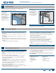
1. For continuous slab
landings, apply a
1/4" bead of sealant
around the sill where
it meets the slab.
Leave 1" gaps at the
weep holes as shown.
2. Ensure sealant on
back dam of the sill
pan fully seals to
the inside face of
the sill. Apply more
sealant as necessary
to ensure an airtight
seal.
7
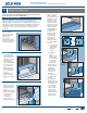
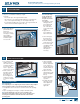
FLASH PATIO DOOR
PREPARE FLASHING
1. Cut pieces of self-adhesive ashing to length
as follows:
• One header piece 14" longer than the header
• Two side pieces: for continuous slab landings, 5" longer than the
sides, or for step-down landings, 5" + the height of the step
• For step-down landings only, one sill piece 10" longer than the sill
and 1" narrower than the height of the step
SPRAY ADHESIVE/PRIMER
2. Apply spray adhesive
per manufacturer’s
instructions
(protect door from
overspray) to nailing
n, sheathing,
and building wrap
around the patio
door as shown.
S
p
r
a
y
A
d
h
e
s
i
v
e
6"
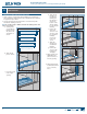
5. Center and apply
the header piece
above the header.
6. Press the ashing
down with a J-roller.
7. Do not allow gaps
or bubbles beneath
self-adhesive
ashing (remove
and replace if
necessary).
APPLY THE SELF-ADHESIVE FLASHING
Note! Keep the edge
of the self-adhesive
ashing as close to
the patio door frame
as possible.
3. If applicable, center
and apply the sill
piece underneath
the sill (bottom
1/2" of the drain
screen must remain
visible).
4. Apply the side
pieces starting 5"
above the header.
5"
5"
5"
Step
height
minus 1"
7"
1"
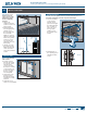
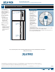
PATIO DOOR ADJUSTMENT
Roller Adjustment
Note! Adjusting door too high may allow water and air leakage. Adjust
rollers just high enough to clear sill track and still roll smoothly.
1. An adjustment screw is located on each lower end of the operating
panel.
2. Open operating panel enough to compare with frame jamb.
Note! Roller adjustment screws are in close proximity to the
attachment screw. Adjust only the lower screw as shown because
loosening the attachment screw will detach the roller from the
operating panel.
3. Using a #2 Philips
head screwdriver,
turn the adjustment
screw clockwise to
raise the panel, and
counterclockwise to
lower the panel.
4. Adjust as needed
until interlocks, grid
patterns and jambs
line up.
5. Test the operating
panel for proper
operation.
6. Re-apply the small
vinyl caps over the
roller adjustment
screw holes if
applicable.
Attachment
screw
Adjustment
screw
Lower panel
Raise panel