
Operating Guide

PRODUCT GUIDE
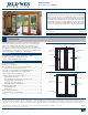
Wood Patio Doors (JPG012)
8
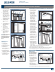
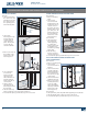
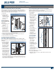
SLIDING/GLIDING ROLLER ADJUSTMENT AND REPLACEMENT
Note! Adjusting door too high may allow water and air leakage.
Adjusting rollers too low can cause panel to drag on lower track.
Adjust rollers just high enough to clear sill track and keep the
weatherstrip hidden when the door is closed. You may need to raise
one roller and lower the other. Check by almost closing the door and
looking for an even, parallel gap.
1. Adjustment holes
are located at both
lower ends on the
face of the panel,
or on the end of the
operating panel(s).
Remove small plastic
plugs from each hole
(ifpresent).
2. Open operating
panel enough
to compare with
framejamb.
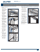
3. Lift the panel to take
the weight off of the
roller and turn the
adjustment screw in
1/4 turn increments
with a screwdriver
(do not use a power
driver). Some panels
with face adjustment
holes will have a (+)
or a (-) sign in the
adjustment hole. If a
sign is not present, or
it is a (+), clockwise
rotations will lower the panel, and counterclockwise rotations will
raise the panel. Opposite adjustments apply to the (-) sign. Use a
Phillips screwdriver for end adjusted rollers. Clockwise rotations will
raise the panel, and counterclockwise rotations will lower the panel.
4. Adjust as needed until interlocks, grid patterns, and jambs line up.
5. Test the operating panel for proper operation.
6. Re-apply the small plastic caps over the roller adjustment screw holes
if applicable.
ROLLER ASSEMBLY REPLACEMENT
1. Remove operating panel and lay on at surface.
2. At the bottom of the panel, remove both Phillips screws from
rollerassembly.
3. Remove roller assembly.
4. Install new roller assembly in the same place.
Face Adjusted Roller
End Adjusted Roller
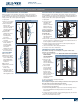
HARDWARE REPLACEMENT AND ADJUSTMENT - CONTINUED
LOCK REPLACEMENT AND ADJUSTMENT
Locking mechanisms have changed over time and can be very complex.
The following instructions provide basic lock servicing procedures, but
cannot fully explain every possible situation. For help with identifying
your lock type and for specic instructions not found here, please
contact us.
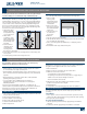
SINGLE-POINT SLIDING DOOR HANDLE AND LOCK REPLACEMENT
Compare replacement
handle set or lock to
your existing hardware
to make sure you
have the correct new
hardware.
When removing screws
and parts, keep track of
their exact locations for
reinstallation.
1. Remove screws from
the interior handle.
2. Remove handles
(interior and
exterior), the interior
lock lever and the exterior keyway lock.
3. Remove the attachment screws from the lock assembly in the
dooredge.
4. Remove the lock assembly.
5. To install, reverse these instructions.
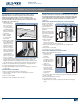
SINGLE-POINT SLIDING DOOR LOCK ADJUSTMENT
Make horizontal adjustment as follows:
1. Open panel and
locate the lock
assembly.
2. Use a small
screwdriver to turn
the adjustment screw
located on the face
of the lock.
3. Turn the screw
counterclockwise to
reduce the length
of the latch hook.
Turn screw clockwise
to lengthen the
latchhook.
4. If necessary, shims can be ordered and placed behind the strike plate.
Please contact us.
Make vertical adjustments as follows:
1. Loosen the keeper screws.
2. Adjust keeper up or down to align with lock strike and retighten
screws.
Single-Point Sliding Door Lock Replacement
Single-Point Sliding Door Lock Adjustment
Adjustment
screw
Attachment
screws
Lock
hook
Handle
lever
Interior
handle
Strike
plate
Lock hook
adjustment
screw