
Operating Guide
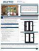

PRODUCT GUIDE
Wood Patio Doors (JPG012)
9
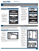
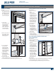
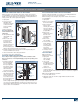
MULTI-POINT SLIDING DOOR HANDLE SET REPLACEMENT
When removing screws and parts, keep track of their exact locations
for reinstallation. To replace, follow instructions included with the new
handle set. Compare replacement components to existing hardware to
verify you have the correct replacement part(s).
1. Open panel.
2. Loosen set screw
with 4mm allen
wrench from interior
or exterior handle
(only one handle,
notboth).
3. Remove handles.
Note! One handle will
remain attached to the
spindle bar.
4. Slide spindle bar and
other handle out
ofpanel.
5. Remove the screw
in the panel edge
to remove the
dead bolt latch if
present. If there is no
attachment screw,
the dead bolt latch is
xed to the faceplate and will remove with it.
6. From the interior, unscrew and remove both face plates (they are
connected with the same screw).
7. Unscrew and remove the locking mechanism.
8. To install, reverse these instructions.
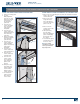
MULTI-POINT SLIDING LOCK ADJUSTMENT
Note! This procedure only applies to doors with a continuous strike
plate. For all others, or for help identifying your specic product, please
contact us.
1. Insert the guide pin
that came with the
door (or available
from your supplier)
into the hole in the
locking mechanism
above the latch.
Screw it in by hand.
2. Gently close the door.
The guide pin should
enter a keeper hole
in the keeper. If not,
loosen the screws in
the keeper and move
the keeper up or
down to align with the guide pin. Compare replacement handle set
or lock to your existing hardware to make sure you have the correct
new hardware. When removing screws and parts, keep track of their
exact locations for reinstallation.
Multi-Point Sliding Door Handle and Lock
Mechanism Replacement
Multi-Point Sliding Door Lock Replacement
Guide
pin
Dead bolt
screw
Set
screw
Spindle
bar
Face
plate
Locking
mechanism
Dead bolt
latch
Handle
Set
screw
Handle
Latch
Face
plates
Spindle
bar
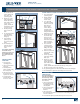
HARDWARE REPLACEMENT AND ADJUSTMENT - CONTINUED
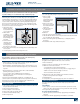
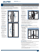
W-2500 SLIDING DOOR HANDLE AND LOCK REPLACEMENT
Compare replacement handle set or lock to your existing hardware to
make sure you have the correct new hardware.
When removing screws and parts, keep track of their exact locations
forreinstallation.
1. Open panel.
2. Remove screws from
the interior handle.
3. Remove handles
(interior and
exterior), the interior
lock lever and the
exterior keyway lock
(if applicable).
4. Remove the
attachment screws
from the lock
assembly in the
dooredge.
5. Remove the
lockassembly.
6. To remove the lock
strike, mark the
current location
in the jamb and
remove the
attachmentscrews.
7. To install, reverse
these instructions.
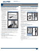
LOCK ADJUSTMENT
Make horizontal
adjustment as follows:
1. Open panel
and locate the
lockassembly.
2. Use a small
screwdriver to turn
the adjustment screw
located on the face
of the lock.
3. Turn the screw
counterclockwise to
reduce the length of the latch hook. Turn screw clockwise to lengthen
the latch hook.
Make vertical adjustments as follows:
1. Loosen the strike screws.
2. Adjust the strike up or down to align with the latch hooks and
retighten screws.
Adjustment
screws
Attachment
screws
Attachment
screws
Lock
hook
Handle
lever
Interior
handle
W-2500 Handle and Lock Assembly
W-2500 Lock Strike