
Operating Guide


PRODUCT GUIDE
Wood Casement & Awning Windows (JPG009)
11
HARDWARE REPLACEMENT & ADJUSTMENT - CONTINUED
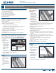
SINGLE - POINT LOCK & KEEPER REPLACEMENT
LOCK REMOVAL
1. Unlock and
open window
BQQSPYJNBUFMZ
2. Unscrew and remove
lock.
Note! A 42" or smaller
casement window may
have one lock. Larger
windows may have
multiple locks on the
same side. Awning
windows will have a
lock on both sides.
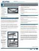
LOCK INSTALLATION
1. Slide replacement
lock into existing
groove.
2. Replace screws.
$MPTFBOEMPDLXJOEPX
KEEPER REPLACEMENT
Replacement keepers
may look different
than the original.
Always install the
new keeper in the
same place and
facing the same
direction as the old
keeper.
1. Open sash to expose
keepers.
2. Remove screws and
keeper.
*OTUBMMOFXLFFQFS
on sash in the
same location and
direction as the old keeper (open side of keeper should face sash
edge).
4. Check lock operation.
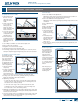
MULTI - POINT LOCK REPLACEMENT - CASEMENT WINDOWS ONLY
LOCK REMOVAL (ILLUSTRATION IN NEXT COLUMN)
1. Remove the screen.
2. Open the window half way.
1VMMPGGIBOEMFBOESFNPWFMPDLDPWFSQMBUFBOETFUBTJEF
4. Score (with utility knife) and remove wood operator cover, head
screen stop, and side screen stop on lock side by gently prying with
large putty knife.
Note! A lock bar has one to three locking points depending on window
size.
6OTDSFXBOESFNPWFMPDLIBOEMFESJWFMPDBUJOHHVJEFTBOEMPDLCBS
LOCK INSTALLATION (ILLUSTRATION IN NEXT COLUMN)
1. Position lock bar and guides on frame in exact previous lock bar
position and install screws through guides.
2. Position lock handle drive and install screws.
3FQMBDFTDSFFOTUPQTBOEXPPEPQFSBUPSDPWFSUSJNXJUIFYJTUJOHOBJMT
and nail holes (carefully tap into place with hammer).
4. Touch-up with paint
or nish if necessary.
3FQMBDFMPDLDPWFS
plate and reattach
handle.
5FTUPQFSBUJPOJGOPU
operating properly,
call us for assistance.
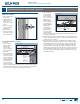
KEEPER REPLACEMENT
1. Remove the screen.
2. Open the window
half way.
-PDBUFUIFMPDL
keepers on the sash
edge. The number
of keepers varies
depending on the
size of the unit.
4. Unscrew and remove
the keeper(s).
3FQMBDFUIFOFX
keeper(s) in the exact
position as the old
one, using the same
screws. Do not over
tighten screws and
strip holes.
TILT & TURN LOCKING MECHANISM & KEEPER REPLACEMENT
LOCKING MECHANISM REPLACEMENT
1. Measure sash where
the hardware is
mounted and contact
us to order new
hardware.
2. Remove sash.
.BSLBMMMPDLJOHQJO
and screw locations
on the sash before
removing.
4. Remove all
attachment screws.
4FDVSFOFXMPDLJOH
mechanism in the same position as the old hardware.
3FJOTUBMMTBTI
KEEPER REPLACEMENT
1. Note keeper location
and order new
keeper.
2. Open sash.
3FNPWFBUUBDINFOU
screws and remove
keeper.
4. Secure new keeper in
the same position as
the old keeper.
$MPTFBOEMPDLTBTI
and test for proper
operation. Remove
BOESFJOTUBMMJGOFDFTTBSZ"EKVTUQJOJGOFDFTTBSZ
Lock
handle
Lock handle
drive
Lock cover
plate
Lock bar
Lock
locating
guide
Keepers
on sash
Lock
keeper
Sash
Lock
Locking
pin
Attachment
screw