
Operating Guide


PRODUCT GUIDE
Wood Casement & Awning Windows (JPG009)
12
HARDWARE REPLACEMENT & ADJUSTMENT - CONTINUED
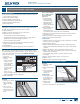
FRENCH CASEMENT LOCK ADJUSTMENT
"EKVTUNFOUNBZCF
necessary if slide bolts
do not line up properly
with the keepers. If
QSPQFSMZBEKVTUFEUIF
slide bolts will snugly
engage the keepers
and provide a tight t
when the sash is locked.
1. With 4mm Allen
wrench, turn slide
bolt slightly (1/4
turn) clockwise or
counterclockwise at
each locking point.
5FTUBEKVTUNFOUBOE
SFBEKVTUJGOFDFTTBSZ
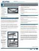
SHOOT BOLT REPLACEMENT
Some radius French
casement windows
have shoot bolts at
the top of the locking
mechanism that slide
into a keeper in the
header.
REMOVAL
1. Remove screws
from shoot bolt and
remove cover from
bottom screw.
2. Pull xed gear top
away from sash to
disengage teeth on
xed gear and shoot
bolt.
8IJMFIPMEJOHVQ
xed gear, slide
shoot bolt out and
remove.
INSTALLATION
1. Position shoot bolt
with top even with sash top.
4MJEFCPUUPNPGTIPPUCPMUVOEFSUPQPGåYFEHFBSFOHBHFUFFUI
3FQMBDFDPWFSPOCPUUPNTDSFXSFQMBDFTDSFXT
4. Replace screws to top of shoot bolt.
$MPTFXJOEPXBOEDIFDLPQFSBUJPOJGOPUPQFSBUJOHQSPQFSMZSFNPWF
BOESFJOTUBMMJGOPUTVDDFTTGVMDBMMVTGPSBTTJTUBODF
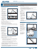
SHOOT BOLT KEEPER REPLACEMENT
The shoot bolt keeper is
located in the header.
1. Remove screws and
keeper.
2. Reinstall in same
position.
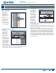
FRENCH CASEMENT MULTI-POINT LOCK REPLACEMENT
REMOVAL
1. Note exact part locations before disassembly
2. Unlock and open sash to expose lock.
3FNPWFQBSUTGSPNUIFFYUFSJPSTJEFBOECPUUPNUPUPQBTGPMMPXT
4. Remove handle for easier access to screws.
6OTDSFXBOESFNPWFHFBSDPOOFDUPSMPDBUFEPOTBTIJOUFSJPS
6OTDSFXBOESFNPWFHFBSIPVTJOHPOTJEFBOEVOEFSTBTI
%JTFOHBHFåYFEHFBSUFFUIGSPNUPQSPMMFSVOJUHFBSUFFUISFNPWF
xed gear.
6OTDSFXBOESFNPWFUPQSPMMFSVOJUBOEIFBESPMMFSVOJU
INSTALLATION
1. Install parts from top to bottom as follows:
1PTJUJPOIFBESPMMFSBOEUPQSPMMFSVOJUSFQMBDFBOEUJHIUFOTDSFXT
&OHBHFåYFEHFBSUFFUIJOUPUPQSPMMFSVOJUHFBSUFFUI
Note! Top teeth of xed gear should line up with top teeth of top roller
unit and slide bolts should be in up position.
1PTJUJPOHFBSIPVTJOHSFQMBDFBOEUJHIUFOTDSFXTPOTJEFBOECPUUPN
of sash.
Note! At this point the
bottom slide bolt (locking
point that slides into
the keeper) should be
positioned away from the
hinge side of the sash and
the top slide bold should
be positioned toward the
hinge side of the sash.
1PTJUJPOHFBS
connector at bottom
JOUFSJPSTJEFPGTBTI
replace and tighten
screws.
$MPTFXJOEPX
and check lock for
proper operation.
Remove and reinstall the lock system if necessary or call our service
department for assistance.
Slide bolt
Cover
Shoot
bolt
Fixed gear
Line up
teeth
Head keeper
Sill keepers
installed in
opposite
sash
Handle
ATCZ
connector
Gear
housing
Fixed gear
Gear teeth
Head roller
unit
Top roller
unit
Sill keeper