
Instructions / Assembly
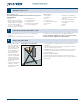
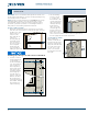
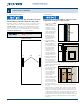
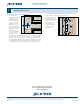
Table Of Contents

5
3
Installation Instructions
for Interior Door Slabs (JII110)
INSTALL SLAB (CONTINUED)
3/16"
1/4"
Slab
Hinge
jamb
Stop
6 7/8"
7"
Plumb
line
<LB LB><LB>
Install Hinges
Three hinges are recommended for slabs up to 84" in
height and four hinges for slabs over 84".
1. If re-using the existing
frame, verify the
existing hinge locations
are plumb, or all in a
straight line vertically.
Position the new hinges
in the existing locations
and modify the hinge
routes as necessary.
Match the slab to
the jambs using the
followinginstructions
(skip to step 3).
2. If installing a new
frame, measure down
from the underside of
the head jamb 7" to
position the top of the
top hinge. Measure
up from the bottom
of the slab 10" to
position the bottom
of the bottom hinge.
Place the middle hinge
halfway in between.
3. When marking the slab
for hinges, make sure
the measurement from
the top of the slab
to the top of the hinge route is 1/8" smaller than the distance from
the head jamb to the top of the top hinge. This will allow 1/8" gap
between the slab and head jamb.
4. When marking the
slab, the distance from
the inside face to the
back of the hinge
route should be 1/16"
less than the depth
of the hinge route on
thehinge jamb.
5. Using a template, mark
the hinge jambs and
slab where the hinges
will be mounted. Using
a chisel or router, notch
the jamb and slab for
the outline of the hinge leaves and no deeper than the thickness of
the leaves.
6. Using the hinge as a template, mark screw hole locations and drill
pilot holes for all screws. If possible, it may be easier to remove the
hinge pin to separate the hinge leaves. Use a hammer and a punch
to drive the pin from the open end. Install the hinge leaves separately
on the jambs and slab (we recommend using a hand screwdriver
when installing screws into the slab to prevent stripping). Then, hang
the slab in the frame by aligning the hinge leaves and re-install the
hinge pins.
Lock Block Identication
Markings indicate the top edge and which side of the
slab should be positioned towards the strike jamb.
If installing a hollow core door that does not have a lock set hole, refer
to the top edge of the door. There will be an inked stamp with either
"<LB, LB> or <LB>". The arrow next to the LB indicates the lock block
location. Using the lock set manufacturer’s instructions and template,
drill for lock set. Reference section 4 for additional lock set information.
Interior Door Division Chiloquin
CARB ID: Phase 1
California 93120 Phase 1 compliant
for formaldehyde
<LB> 1/06 x 6/08 1 - 3/8 HC M50J52 COLONIST 6P PB - KENNE
DC031710J1 662 Y
Top Rail Door Identication
Lock block stamp
Lock Block Locations