Professional 48², 36², 30² Gas Range Models 403 WEST FOURTH STREET, NORTH · NEWTON, IA 50208 Retain this manual for future reference. (17663 Rev.
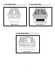
30² GAS RANGE MODEL 36² GAS RANGE MODEL MODEL PRG3010 MODEL PRG3610 48² GAS RANGE MODEL MODEL PRG4810 2
TABLE OF CONTENTS INTRODUCTION MODEL IDENTIFICATION . . . . . . . . . . . . . . . . . . . . . . . . 2 The features offered by the Jenn-Air professional series of gas ranges are certain to make the cooking experience more enjoyable and provide the novice or the experienced chef with years of enjoyment. A large capacity gas oven with a gas infrared broiler is included on the 30², 36² and 48² ovens.
IMPORTANT INSTALLATION INSTRUCTIONS STEP 1: VENTILATION REQUIREMENTS Tested in accordance with ANSI Z21.1-1993 Standard for Household Cooking Gas Appliances. A suitable exhaust hood must be installed above the range. The following chart indicates the minimum blower capacity recommended for hood ventilation. (Table 1). These ranges must be installed in conjunction with a suitable overhead vent hood. (See Step: 1 for Ventilation Requirements).
STEP 2: CABINET PREPARATION 1. The range is a free-standing unit. If the unit is to be placed adjacent to cabinets, the clearances shown in Figures 2A/B/C are required. The same clearances apply to island installations. 2. The range can be placed in various positions with respect to the cabinet front, with the front either flush or projecting, depending on the countertop depth. See Figure 3A/B and Table 2 (side view of range) for dimensions. 3.
5. Any openings in the wall behind the range and in the floor under the range must be sealed. and Figure 3B indicate the space required for each type of backguard. 6. When there is less than a 12² clearance between combustible material and the back edge of the range, (above the cooking surface) Jenn-Air Stub Back or High Shelf Backguard must be installed. These parts must be ordered separately, except for the PRG3010 which comes equipped with a Low Back. Figure 3A 7.
STEP 3: UNPACKING, MOVING AND PLACING THE RANGE CAUTION PROPER EQUIPMENT AND ADEQUATE MANPOWER MUST BE USED IN MOVING THE RANGE TO AVOID DAMAGE TO THE UNIT OR THE FLOOR. THE UNIT IS HEAVY AND RESTS ON ADJUSTABLE STEEL LEGS. DO NOT LIFT THE RANGE BY THE OVEN DOOR HANDLES!! The 36² range has a shipping weight of approximately 408 pounds or 354 pounds after removal of packing materials.
It is important that the two screws retaining the kick panel are secure to prevent accidental access to live electrical components and wires (see Figure 5). To remove the door, open the door and hold it all the way open. Close the hinge latches (see Figure 8) and release the door. The door can then be removed by gently lifting and pulling the door, with the hinges up and out of the frame. The hinges are assembled to the door and will be removed from the frame when the door is lifted upward.
ANTI-TIP DEVICE INSTALLATION INSTRUCTIONS NOTE: A risk of range tip over exists if the appliance is not installed in accordance with the installation instructions provided. The proper use of this device minimizes the risk of TIP-OVER. In using the device the consumer must still observe the safety precautions as stated in the USE and CARE MANUAL and avoid using the oven door and/or kick plate as a step stool. For SAFETY CONSIDERATIONS as well as optimum performance adjust the range so that it is level.
STEP 4: ELECTRICAL CONNECTIONS STEP 5: GAS REQUIREMENTS Power Requirements Verify the type of gas supplied to the location. 120 VAC, 60 Hz., single phase. The range is shipped from the factory set up and adjusted for natural gas or LP gas (propane), depending on model ordered. PRG3010 4 Amp. Max. PRG3610 7 Amp. Max. PRG4810 - 13 Amp. Max. (Use 15 Amp. Circuit) Natural Gas Requirements Connection: 1/2² N.P.T. Minimum 5/8² dia. flex line. Pressure: 6² to 14² W.C.
STEP 6: BACKGUARD INSTALLATION Oven and Griddle Burners The backguard must be installed when there is less than a 12² clearance between combustibles and the back of the range above the cooking surface (see Figure 3B). Check for the proper burner flame characteristics and adjust air shutters if necessary (see figures 13 - 14). Each valve and air shutter is individually tested and adjusted prior to shipment.
Surface Burners INSTALLER FINAL CHECK LIST The surface burners are not adjustable. Proper operation is achieved when the correct orifices for the gas supply are installed at the factory, based on model ordered. j j j j j * If the top burner does not ignite, check the spark igniter by listening for a clicking sound. If you do not hear the igniter click, turn off the burner. Check for a tripped circuit breaker, blown fuse, or poor wire connection to the igniter.
JENN-AIR PRG3010 WIRING DIAGRAM Part No.: 16565-50 12/03 Rev.
LF LF LR LR RF RF RR RR JENN-AIR PRG3010 WIRING SCHEMATIC Part No.: 16565-50 12/03 Rev.
JENN-AIR PRG3610 WIRING DIAGRAM Part No.: 16560-50 12/03 Rev.
JENN-AIR PRG3610 WIRING SCHEMATIC Part No.: 16560-50 12/03 Rev.
JENN-AIR PRG4810 WIRING DIAGRAM Part No.: 16561-50 12/03 Rev.
JENN-AIR PRG4810 WIRING SCHEMATIC Part No.: 16561-50 12/03 Rev.
MISE EN SERVICE Cuisinières à gaz professionnelles de 121,9, 91,4 et 76,2 cm WEST FOURTH STREET, NORTH · NEWTON, IA 50208, ÉTATS- UNIS Veuillez conserver ce manuel pour référence ultérieure.
MODÈLE DE CUISINIÈRE À GAZ DE 76,2 CM MODÈLE DE CUISINIÈRE À GAZ DE 91,4 CM MODÈLE PRG3010 MODÈLE PRG3610 MODÈLE DE CUISINIÈRE À GAZ DE 121,9 CM MODÈLE PRG4810 2
TABLE DES MATIÈRES INTRODUCTION IDENTIFICATION DU MODÈLE . . . . . . . . . . . . . . . . . . . 2 Les caractéristiques des cuisinières à gaz professionnelles Jenn-Air ne manqueront pas de rendre vos activités culinaires encore plus agréables et d’apporter au novice comme au cordon bleu des années d’agrément. Les fours de 76,2, 91,4 et 121,9 cm comportent un four de grande capacité avec gril à gaz à infrarouges.
CONSIGNES IMPORTANTES DE MISE EN SERVICE ÉTAPE 1 : BESOINS EN ÉVACUATION ET APPORT D’AIR Fonctionnement vérifié conformément à la norme ANSI Z21.1-1993 pour les appareils de cuisson ménagers fonctionnant au gaz. Une hotte d’évacuation appropriée doit être posée au-dessus de la cuisinière. Le tableau suivant indique la capacité recommandée pour le ventilateur (voir le tableau 1). La mise en service de ces cuisinières doit comporter une hotte d’évacuation de puissance appropriée.
ÉTAPE 2 : PRÉPARATION DE L’ARMOIRE la profondeur du comptoir. Voir la figure 3A/B et le tableau 2 (vue du côté de la cuisinière) pour les dimensions. 3. L’alimentation en électricité et en gaz doit être dans les zones indiquées aux figures 2 et 4. 4. La profondeur maximum d’armoires en hauteur posées de chaque côté de la hotte d’évacuation doit être de 33 cm. 1. La cuisinière est amovible. Si elle doit être placée adjacente à des armoires, les dégagements indiqués à la figures 2A/B/C sont exigés.
5. Toute ouverture dans le mur à l’arrière de la cuisinière et dans le plancher sous la cuisinière doit être bouchée. est déjà équipé d’un dosseret court. Les figures 3A et 3B indiquent l’espace requis pour chaque type de dosseret. 6. S’il y a moins de 30,5 cm entre un matériau combustible et le bord arrière de la cuisinière (au-dessus de la surface de cuisson), il faut poser un dosseret extra court ou un dosseret Jenn-Air avec tablette.
ÉTAPE 3 : DÉBALLAGE, DÉPLACEMENT ET PLACEMENT DE LA CUISINIÈRE ATTENTION IL FAUT UTILISER L’ÉQUIPEMENT APPROPRIÉ ET AVOIR DU PERSONNEL SUFFISANT POUR DÉPLACER LA CUISINIÈRE AFIN D’ÉVITER D’ABÎMER L’APPAREIL OU LE PLANCHER. L’APPAREIL EST LOURD ET REPOSE SUR DES PIEDS RÉGLABLES EN ACIER. NE PAS SOULEVER LA CUISINIÈRE EN LA TENANT PAR LES POIGNÉES DU FOUR !! Le poids d’expédition de la cuisinière de 91,4 cm est d’environ 185 kg avec l’emballage et de 161 kg une fois les matériaux d’emballage enlevés.
Pour enlever la porte, l’ouvrir et la maintenir complètement ouverte. Fermer les verrous de charnière (voir la figure 8) et dégager la porte. La porte peut maintenant être enlevée en tirant doucement pour la soulever jusqu’à ce que les charnières soient sorties de l’encadrement. Les charnières sont fixées à la porte et s’enlèvent de l’encadrement quand la porte est soulevée et retirée de l’encadrement. réglables avant pour mettre l’avant de la cuisinière de niveau.
MISE EN PLACE DU DISPOSITIF DE STABILISATION REMARQUE : La cuisinière risque de basculer si elle n’est pas mise en place conformément aux consignes de mise en service fournies. Si le dispositif de stabilisation est utilisé correctement, il réduit le risque que la cuisinière ne - BASCULE.
ÉTAPE 4 : RACCORDEMENT À L’ÉLECTRICITÉ ÉTAPE 5 : ALIMENTATION EN GAZ Vérifier le type de gaz fourni. Installation électrique nécessaire Cet appareil a été expédié de l’usine réglé sur le gaz naturel ou le gaz GPL (propane) selon le modèle commandé. 120 VAC, 60 Hz., monophasé. PRG3010 4 A max. PRG3610 7 A max. PRG4810 - 13 A max. (Utiliser un circuit de 15 A.) Caractéristiques de l’alimentation en gaz naturel Raccordement : conduite flexible 1/2 NPT de 1,5 cm de diam. min.
Brûleurs du four et du gril ÉTAPE 6 : POSE DU DOSSERET S’assurer que la flamme du brûleur présente bien les caractéristiques désirées et régler les obturateurs d’air s’il y a lieu (voir les figures 13 à 14). Chaque bouton de commande et chaque obturateur est testé individuellement et ajusté avant l’expédition. Normalement, aucun réglage n’est nécessaire ; toutefois, les vibrations au cours du transit ou des variations dans l’alimentation en gaz local peuvent rendre des réglages mineurs nécessaires.
Brûleurs de la surface de cuisine LISTE DE VÉRIFICATION DE L’INSTALLATEUR Les brûleurs de la surface de cuisine ne sont pas réglables. Les brûleurs functionnent correctement quand les orifices convenables à alimentation de gaz sont installés en usine selon le modèle commandé. j Placement de la cuisinière. j Dégagement spécifié maintenu par rapport aux surfaces des armoires.
SCHÉMA DE CÂBLAGE PRG3010 JENN-AIR DISP. ALLUMAGE AVG 70 VE ARG 20 NR 71 VE AVD AVD 21 NR 74 VE ARD ARD 22 NR 75 VE MODULES DE RÉALLUMAGE BC NR BC 72 VE 73 VE DÉBRANCHEMT RÉSEAU NR NR BC NR 10 BC B-- L 4 NR B-- N BC 11 BC 28 J 5 J 8 BC 18 NR 35 BC 42 NR GRIL 4 NR 37 BR ROBINET DOUBLE NR 36 NR FOUR ALLUM. FOUR BROIL ALLUM. GRIL IGN. 28 BC 10 BC 39 NR 29 NR 33 BC 32 BC 11 BC TSTAT FOUR TÉMOIN CHAUFF. 35 BC 5 J 30 J 29 NR 31 J 34 BR COMMUT. ÉCLAIR.
Référence : 16565-50 12/03 Rév. C 14 BC BOUTONS RÉGLAGE MODULES DE RÉALLUMAGE DISP. ALLUMAGE AVG AVG NR BC ARG ARG AVD AVD ARD ARD NF FOUR DISP. ALLUM. FOUR DISP. ALLUM. GRIL BOUTON FOUR BOUTON GRIL GRIL THERMOSTAT FOUR (CYCLES) TÉMOIN CHAUFF. MOT. CHAL. TOURN. COMMUT. MOTEUR ÉCLAIRAGE FOUR ÉCLAIRAGE FOUR COMMUT. ÉCLAIR.
SCHÉMA DE CÂBLAGE PRG3610 JENN-AIR 19 NR DISP. ALLUMAGE AVG AVG 70 VE 20 NR ARG ARG 71 VE AVC 21 NR AVC 22 NR 75 VE ARC ARC 48 NR 76 VE AVD AVD 77 VE ARD 49 NR ARD 78 VE MODULES DE RÉALLUMAGE Référence : 16560-50 12/03 Rév.
Référence : 16560-50 12/03 Rév. C 16 BC BOUTONS RÉGLAGE MODULES DE RÉALLUMAGE DISP. ALLUMAGE AVG AVG NR BC ARG ARG AVC AVC ARC ARC AVD AVD ARD ARD NF FOUR DISP. ALLUM. FOUR DISP. ALLUM. GRIL BOUTON FOUR BOUTON GRIL GRIL THERMOSTAT FOUR (CYCLES) TÉMOIN CHAUFF. MOT. CHAL. TOURN. COMMUT. MOTEUR ÉCLAIRAGE FOUR ÉCLAIRAGE FOUR COMMUT. ÉCLAIR.
SCHÉMA DE CÂBLAGE PRG4810 JENN-AIR DISP. ALLUMAGE AVG AVG 19 NR 70 VE ARG ARG 20 NR 71 VE AVC AVC 21 NR 75 VE ARC ARC 22 NR AVD 76 VE AVD 48 NR ARD ARD 72 VE MODULES DE RÉALLUMAGE BC 78 VE BC NR 49 NR NR NR BC NR BC 73 VE 74 VE 18 NR 8 BC 3 NR 10 BC B-- L 5 4 J NR B-- N 11 BC 28 BC 38 BC 6 NR 13 BC 12 BC 35 BC COMMUT. ÉCLAIR. 37 NR FOUR 36 NR 4 NR 42 NR NR GRIL ROBINET DOUBLE ALLUM. FOUR ALLUM.
Référence : 16561-50 12/03 Rév. C 18 NR BC BOUTONS RÉGLAGE MODULES DE RÉALLUMAGE DISP. ALLUMAGE AVG AVG NR BC ARG ARG AVC AVC ARC ARC AVD AVD ARD ARD FOUR 30 CM (12 PO) (SANS GRIL) GRIL DE SURFACE NF FOUR DISP. ALLUM. FOUR DISP. ALLUM. GRIL BOUTON FOUR BOUTON GRIL GRIL TÉMOIN CHAUFF. MOT. CHAL. TOURN. COMMUT. MOTEUR THERMOSTAT FOUR (CYCLES) ÉCLAIRAGE FOUR ÉCLAIRAGE FOUR COMMUT. ÉCLAIR.
MANUAL DE INSTALACIÓN Modelos profesionales de estufas de gas de 48”, 36” y 30” Conserve este manual como referencia futura. 403 WEST FOURTH STREET, NORTH · NEWTON, IA 50208 EE.UU.
MODELO DE ESTUFA DE GAS DE 30²² MODELO DE ESTUFA DE GAS DE 36²² MODELO PRG3010 MODELO PRG3610 MODELO DE ESTUFA DE GAS DE 48²² MODELO PRG4810 2
ÍNDICE INTRODUCCIÓN IDENTIFICACIÓN DEL MODELO . . . . . . . . . . . . . . . . . 2 Las características que ofrecen las estufas de gas de la serie profesional de Jenn-Air harán que la experiencia de cocinar sea más placentera y le darán al principiante o al cocinero experimentado muchos años de servicio fiel. Los hornos de 30”, 36” y 48” se incluyen un horno de gas de gran capacidad y un asador infrarrojo de gas.
INSTRUCCIONES IMPORTANTES DE INSTALACIÓN PASO 1: REQUISITOS DE VENTILACIÓN Debe instalarse encima de la estufa una campana de escape apropiada. La tabla siguiente indica la capacidad mínima de ventilación que se recomienda para la ventilación con campana. (Tabla 1). Pruebas realizadas en conformidad con Estándar ANSI Z21.1-1993 para electrodomésticos de gas para cocinar. Estas estufas deben instalarse en conjunto con una campana superior de ventilación apropiada.
PASO 2: PREPARACIÓN DEL GABINETE 1. La estufa es una unidad independiente. Si se colocará adyacente a los gabinetes, se requerirán los espacios libres que se muestran en la figuras 2A/B/C. Los mismos espacios libres se aplican a las instalaciones en islas. 2. La estufa puede colocarse en varias posiciones con respecto al frente del gabinete, con el frente al ras o realzado, dependiendo de la profundidad del mostrador.
5. Deben sellarse las aberturas en la pared posterior y en el piso debajo de la estufa. viene equipado con el protector posterior bajo. Las figuras 3A y 3B indican el espacio que se requiere para cada tipo de protector posterior. 6. Cuando haya menos de 12” de espacio libre entre el material combustible y el borde posterior de la estufa, (por encima de la superficie para cocinar), debe instalarse un protector posterior corto o uno con repisa alta de Jenn-Air.
PASO 3: DESEMPACADO, TRANSPORTACIÓN Y COLOCACIÓN DE LA ESTUFA PRECAUCIÓN DEBE UTILIZARSE EL EQUIPO Y MANO DE OBRA APROPIADOS CUANDO SE TRANSPORTE LA ESTUFA PARA EVITAR CAUSAR DAÑOS A LA UNIDAD O AL PISO. LA UNIDAD ES PESADA Y SE APOYA EN PATAS AJUSTABLES DE ACERO. ¡NO LEVANTE LA ESTUFA SUJETÁNDOLA POR LAS ASAS DE LA PUERTA! La estufa de 36” tiene un peso de embarque de aproximadamente 408 libras o 354 libras después de quitarle los materiales de embalaje.
Es importante que los dos tornillos que retienen el panel plegable estén seguros para prevenir el acceso accidental a los componentes y alambres eléctricos energizados (vea la figura 5). Para quitar la puerta, ábrala y sosténgala completamente abierta. Cierre los pasadores de las bisagras (vea la figura 8) y libere la puerta. Ésta puede quitarse levantándola suavemente, con las bisagras hacia arriba y fuera del marco.
INSTALACIÓN DEL DISPOSITIVO ESTABILIZADOR NOTA: Existe un riesgo de ladeo de la estufa si ésta no se instala de acuerdo con las instrucciones de instalación provistas. El uso apropiado de este dispositivo minimiza el riesgo de LADEO. Al usar el dispositivo el cliente debe continuar observando las precauciones de seguridad según se establece en el MANUAL DE USO Y CUIDADO y evitar usar la puerta del horno o la placa plegable como banquillo.
PASO 4: CONEXIONES ELÉCTRICAS PASO 5: REQUISITOS DE GAS Requisitos de energía Verifique el tipo de gas que se surte al lugar. 120 VCA, 60 Hz., monofásico. El electrodoméstico se embarca de fábrica ajustado al gas natural o al gas LP (propano), según el modelo pedido. PRG3010 4 Amperios máx. PRG3610 7 Amperios máx. PRG4810 - 13 Amp. máx. (Use circuitos de 15 Amperios) Requisitos de gas natural Conexión: 1/2² N.P.T. Cuando menos tubería flexible de 5/8” de diámetro.
Quemadores del horno y de la plancha PASO 6: INSTALACIÓN DEL PROTECTOR POSTERIOR Verifique las características de la llama apropiada del quemador y ajuste los obturadores de aire si fuera necesario (vea las figuras 13 — 14). Cada válvula y obturador de aire se prueba independientemente y se ajusta antes de embarcarse.
Quemadores superiores LISTA DE VERIFICACIÓN FINAL DEL INSTALADOR Los quemadores superiores no son ajustables. Los quemadores funcionan correctamente cuando los orificios apropriados para la fuente de gas están instalados en fábrica, según el modelo pedido. j Colocación de la unidad. j El espacio libre especificado se mantuvo en las *Si una de las quemadores superiores no se enciende, compruebe el encendedor escuchando un sonido que chasca. Si usted no oye el tecleo del encendedor, apague el quemador.
DIAGRAMA DE CABLEADO JENN-AIR PRG3010 ENCENDE-DORES ID ID 70 TR IT 71 TR 57 AN 20 NG DD DD 74 TR 58 AN 21 NG DT DT 75 TR 59 AN 22 NG MÓDULOS DE REENCENDIDO BL NG BL 72 TR 73 TR DESCONEXIÓN DE SERVICIO NG NG BL NG 10 BL BL-- L 4 NG BL-- N BL 11 BL 28 A 5 A 8 BL 18 NG 35 BL 42 NG PARRILLA 4 NG VÁLVULA DOBLE NG 36 NG HORNO ENC. HORNO ENC. PARRILLA 28 BL 10 BL LUZ CALOR 35 BL 29 NG HORNO EST T 11 BL 32 BL 33 BL 5 A 30 A 31 A 29 NG INT.
Parte No.: 16565-50 12/03 Rev. C 14 BL INTERRUPTORE S VÁLVULA MÓDULOS DE REEN-CENDIDO ENCENDEDORES ID ID NG BL IT IT TT TT DT DT NA HORNEAR ENC. HORNEAR ENC. PARRILLA VÁLVULA HORNEAR VÁLVULA PARILLA NA PARRILLA TERMÓSTATO HORNO (CÍCLICO) NA LUZ CALOR MOTOR CONV. INTERRUPTOR MOTOR NA LUZ HORNO LUZ HORNO INT.
DIAGRAMA DE CABLEADO JENN-AIR PRG3610 19 NR ENCENDE-DORES ID ID IT 57 AN 71 VE 21 NR CD CD 58 AN 22 NR 75 VE CT CT 48 NR 76 VE AN DD DD 49 NR 77 VE 60 AN DT DT 61 AN 78 VE MÓDULOS DE REENCENDIDO 15 AN 70 VE 20 NR IT Parte No.: 16560-50 12/03 Rev.
Parte No.: 16560-50 12/03 Rev. C 16 BL INTERRUPTORE S VÁLVULA MÓDULOS DE REEN-CENDIDO ENCENDEDORES ID ID NG BL IT IT CD CD CT CT TT NA TT NA DT DT NA HORNEAR ENC. HORNEAR ENC. PARRILLA VÁLVULA HORNEAR VÁLVULA PARILLA NA PARRILLA TERMÓSTATO HORNO (CÍCLICO) NA LUZ CALOR MOTOR CONV. INTERRUPTOR MOTOR NA LUZ HORNO LUZ HORNO INT.
DIAGRAMA DE CABLEADO JENN-AIR PRG4810 ENCENDE-DORES ID ID 70 VE IT 71 VE 57 AN 20 NR CD CD 75 VE 58 AN 21 NR CT CT 22 NR 48 NR 76 VE AN DD DD DT 61 AN BL 78 VE BL NG 72 TR MÓDULOS DE REENCENDIDO DESCONEXIÓN DE SERVICIO 49 NR 77 VE 60 AN DT NG NG BL NG BL 73 TR 74 TR 18 NG 8 BL 4 NG BL-- L 3 NG 5 A 28 BL BL-- N 10 BL 11 BL 38 BL 12 BL 6 NG 13 BL INT. LUZ 42 NG PARRILLA 37 NG VÁLVULA DOBLE 4 NG NG 36 NG HORNO ENC. HORNO ENC.
Parte No.: 16561-50 12/03 Rev. C 18 NG BL INTERRUPTORES VÁLVULA MÓDULOS DE REEN-CENDIDO ENCENDEDORES ID ID NG BL IT IT CD CD CT CT TT TT DT DT (SIN PARILLA) HORNO DE 12 PULG ENSAMBLE PLANCHA NA HORNEAR ENC. HORNEAR ENC. PARRILLA VÁLVULA HORNEAR VÁLVULA PARILLA NA PARRILLA NA LUZ CALOR MOTOR CONV. INTERRUP-TOR MOTOR TERMÓSTATO HORNO (CÍCLICO) NA LUZ HORNO LUZ HORNO INT.
NOTAS 19
403 WEST FOURTH STREET, NORTH · NEWTON, IA 50208