
Installation guide

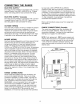
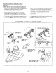

CONNECTING THE RANGE
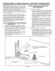
FIGURE 6
3-Wire Service Cord or Conduit Installation
1. Insure that the copper ground strap IS CONNECTED
between the middle post of the main terminal
connection block and the range chassis.
2. If bare copper or aluminum wiring is used, attach
adapter lugs as shown in figure 6. (See Bare Wire
Connection). Torque specifications are shown below.
3. The middle wire of the service cord or ground lead of
3-wire conduit MUST connect to the neutral (middle)
post of the main terminal block. The other two wires of
the service cord or conduit connect to the outside
posts of the main terminal connection block. Polarity is
unimportant. If using bare wire, attach wire to
appropriate lug as shown. Torque specifications are
shown below.
4. An appropriate strain relief for service cord or conduit
MUST be attached to the conduit plate.
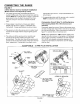
ACCEPTABLE - 3 WIRE PLUG INSTALLATION
CONDUIT
PLATE
MOUNTEDFLUSH
TO WALL
MAIN TERMINAL
CONNECTIONBLOCK
MIDDLEWIRE OF
SERVICECORD
OR CONDUIT
STRAIN
RELIEF
WHITE
ADAPTER
LUGSLOCAIED
IN LITERATUREKIT
8LACK
RARF WIRF TOROUF SPECIFICAIION_
LUG ATTACH[O 10 TERMINAL BLOCK - 2g IN-LB
10-14 20 tg-LU
8 25 IN-LB
4-6 35 Ig-LB
RED
ALTERNATIVF INSTALLATION
FORUSE WITH CONDUIT. _
REMOVE BRACKET. FLIP ///'-.,_I
RE-ATTACHWITH SMALL ///A\\ \/ /A
OUTLETRECEPTACLETO BE -_
ROTATEDAS SHOWNIF NOT_ Z_/ -,.v
FLUSH TO WALL %
FIGURE 6
-6-