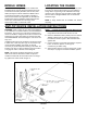
INSTALLER: LEAVE THESE INSTRUCTIONS WITH THE APPLIANCE INSTALLATION MANUAL Electric 30-inch Wide Jenn-Air Radiant Element Range PLEASE KEEP THIS MANUAL FOR FUTURE REFERENCE THE MANUAL IS INTENDED TO ASSIST IN THE INITIAL INSTALLATION AND ADJUSTMENTS OF THE RANGE. SPECIAL WARNING Only qualified personnel should install or service this range. CLEARANCE DIMENSIONS For complete information in regard to installation of Jenn-Air range, see figures 1, 2, 3 and 4.
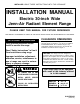
INSTALLATION DRAWINGS (Pages 2, 3 & 4) IMPORTANT PLEASE KEEP FOR THE USE OF THE LOCAL ELECTRICAL INSPECTOR. FIGURE 1 NOTE: Figure may not be representative of actual unit. The 30 inches (76.2 cm) minimum clearance between the top of the cooking surface and the bottom of an unprotected wood or metal cabinet can be reduced to 24 inches (61 cm) minimum when bottom of wood or metal cabinet is protected by not less than 1/4-inch (6.4 mm) thick flame-retardant millboard covered with not less than No.
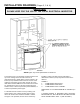
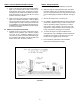
JENN-AIR RANGES 30²² FIGURE 2 FIGURE 3 Notes: 1. Provide for either a 3-wire or 4-wire 120/208, 120/240 volt outlet per applicable cord in shaded area shown. Refer to installation instructions for proper positioning of outlet. 2. Dimension K (figure 4, page 4) is from the wall to the side edge of the oven door. It does not include the curvature of the glass or the depth of the handle. 3. Dimension L (figure 4, page 4) is with the leveler legs adjusted all the way in.
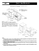
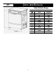
JENN-AIR RANGES 30²² Unity II Slide-In Range Dimensions J Inches Centimeters A 25 63.5 B 24 61.0 C D 30 36 76.2 91.4 E 23 5/8 60.0 F 23 1/4 5 1/2 59.1 14.0 10 29 7/8 25.4 26 3/16 35 3/4 66.5 90.8 2/1/4 5.7 G H J 2* K 3* L M FIGURE 4 * SEE NOTES ON PAGE 3 -4- 75.
MOBILE HOMES LOCATING THE RANGE The installation of a range designed for mobile home installation must conform with the Manufactured Home Construction and Safety Standard, Title 24 CFR, Part 3280 (formerly the Federal Standard for Mobile Home Construction and Safety, Title 24 HUD, Part 280) or, when such standard is not applicable, the Standard for Manufactured Home Installations 1982 (Manufactured Home Sites, Communities and Set-Ups), ANSI A225.1-latest edition, or with local codes.
STEP 3 - Range Installation STEP 2 - Anti-Tip Bracket Installation Options A. Wood Construction: 1. Floor: Locate the center of the two holes identified in figure 5 as “HOLES FOR FLOOR.” Drill a 1/8² (3 mm) pilot hole in the center of each hole (a nail or awl may be used if a drill is not available). Secure the ANTI-TIP bracket to the floor with the two screws provided. Proceed to STEP 3. A. A Jenn-Air range may be installed by one person. B.
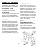
CONNECTING THE RANGE ELECTRIC SUPPLY RANGE CONNECTIONS The range must be installed in accordance with Local and National Electric Code (NEC) ANSI/NFPA No. 70-latest edition. See rating plate for total connected KW rating. Some models are shipped direct from the factory with service cords (pigtails) attached. There are no range connections necessary on these models. Just plug into the range outlet. On models not provided with a service cord, connection to the power supply is necessary.
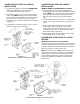
3-WIRE SERVICE CORD OR CONDUIT INSTALLATION 4-WIRE SERVICE CORD OR CONDUIT INSTALLATION 1. Insure that the copper ground strap IS CONNECTED between the middle post of the main terminal connection block and the range chassis. (MOBILE HOMES OR AS REQUIRED BY CODES) 1. The copper ground strap connected between the neutral (middle) post of the main terminal block and the chassis MUST be cut off as shown in figure 9. Save the green ground screw to attach the ground from the 4 wire cord.
INSTALADOR: DEJE ESTAS INSTRUCCIONES CON EL APARATO MANUAL DE INSTALACIÓN Estufa eléctrica Jenn-Air de 30 pulgadas (76,2 cm) de ancho con elemento radiante CONSERVE ESTE MANUAL PARA REFERENCIA FUTURA EL MANUAL TIENE LA FINALIDAD DE AYUDARLE EN LA INSTALACIÓN Y LOS AJUSTES INICIALES DE LA ESTUFA. ADVERTENCIA ESPECIAL Solamente personal calificado debe instalar o darle servicio a esta estufa. Lea las “Instrucciones de seguridad” en el manual de Uso y cuidado antes de utilizar la estufa.
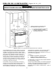
DIBUJOS DE LA INSTALACIÓN (Páginas 10, 11 y 12) IMPORTANTE SÍRVASE CONSERVARLO PARA QUE LO USE EL INSPECTOR ELÉCTRICO LOCAL. MÁXIMA PROFUNDIDAD DE LOS GABINETES ENCIMA DE LA SUPERFICIE DE COCINAR DE 13” [33 cm]. 0” DE ESPACIO LIBRE ENTRE LA CONSTRUCCIÓN COMBUSTIBLE ADYACENTE Y LAS PARTES POSTERIOR Y LATERALES DE LA ESTUFA DEBAJO DE LA SUPERFICIE DE COCINAR. FIGURA 1 NOTA: La figura no es necesariamente representativa de la unidad real.
ESTUFAS JENN--AIR 30²² (76,2 cm) * CUANDO ESTÉ REEMPLAZANDO UNA UNIDAD EXISTENTE, LA MÁXIMA PROFUNDIDAD DEL CORTE DE 23 1/2² (59,7 CM) SERÁ ACEPTABLE. * PROFUNDI DAD DEL CORTE “F” NOTA: EN LAS SUPERFICIES DE LOS MOSTRADORES CON BORDE DELANTERO FORMADO, REBAJE LA SECCIÓN REALZADA PARA LIBRAR LA PARTE SUPERIOR. ANTES DE TRATAR DE INSTALARLA, AJUSTE LAS PATAS NIVELADORAS PARA QUE SE AJUSTEN A ESTA DIMENSIÓN. ALTURA A LA PARTE SUPERIOR DEL MOSTRADOR “D” ÁREA HORIZONTA L MÍNIMA “E” VEA LA NOTA NO.
ESTUFAS JENN--AIR 30²² (76,2 cm) Estufa deslizable Unity II Dimensiones J Pulgadas Centímetros A 25 63,5 B 24 61,0 C D 30 36 76,2 91,4 E 23 5/8 60,0 F 23 1/4 5 1/2 59,1 14,0 10 29 7/8 25,4 26 3/16 35 3/4 66,5 90,8 2 1/4 5,7 G H J 2* K 3* L M FIGURA 4 * VEA LAS NOTAS EN LA PÁGINA 11 -12- 75,9
CASAS MÓVILES UBICACIÓN DE LA ESTUFA La instalación de una estufa diseñada para casas móviles debe estar en conformidad con las Normas de Seguridad y Construcción de Casas Prefabricadas (Manufactured Home Construction and Safety Standard, Título 24 CFR, Parte 3280 (anteriormente Federal Standard for Mobile Home Construction and Safety, Título 24 HUD, Parte 280) o, cuando dichas normas no correspondan, las Normas para Instalaciones en Casas Prefabricadas de 1982 (Manufactured Home Sites, Communities and Se
PASO 2 — Opciones para la instalación del soporte estabilizador PASO 3 — Instalación de la estufa A. Las estufas Jenn-Air puede instalarlas una sola persona. A. Construcción de madera: 1. Piso: Ubique el centro de los dos orificios que se identifican en la figura 5 como “ORIFICIOS PARA EL PISO.” Taladre un agujero piloto de 1/8² (3 mm) en el centro de cada orificio (puede utilizarse un clavo o una lezna si no tiene una broca).
CONEXIÓN DE LA ESTUFA SUMINISTRO ELÉCTRICO CONEXIONES DE LA ESTUFA La estufa debe instalarse de acuerdo con los Códigos Eléctricos Nacionales y Locales (NEC) ANSI/NFPA No. 70, última edición. Vea la placa de clasificación para obtener la clasificación total de kilovatios conectados. Algunos modelos se envían directamente de fábrica con los cordones de servicio (cables flexibles de conexión) sujetos. No es necesario hacer ninguna conexión en estos modelos de estufa.
INSTALACIÓN DEL CORDÓN ELÉCTRICO DE 3 CABLES O DEL CONDUCTOR INSTALACIÓN DEL CORDÓN DE SERVICIO DE 4 CABLES O DEL CONDUCTOR 1. Verifique que la tira de conexión a tierra de cobre ESTÉ CONECTADA entre el poste medio del bloque de conexión del terminal principal y del bastidor de la estufa. 2. El cable medio del cordón o del terminal de tierra del conductor de tres cables DEBE estar conectado al poste neutro (medio) del bloque del terminal principal.
INSTALLER: VEUILLEZ LAISSER CES INSTRUCTIONS AVEC L’APPAREIL MANUEL DE MISE EN SERVICE Cuisinière électrique à éléments tubulaires Jenn-Air de 30 po (76,2 cm) VEUILLEZ GARDER CE MANUEL POUR RÉFÉRENCE ULTÉRIEURE CE MANUEL EST DESTINÉ À FACILITER LA MISE EN SERVICE ET LE RÉGLAGE INITIAUX DE LA CUISINIÈRE. AVERTISSEMENT SPÉCIALE La mise en service et le dépannage de cette cuisinière doivent être réalisés uniquement par du personnel qualifié.
SCHÉMAS DE MONTAGE (Pages 18, 19 et 20) IMPORTANT CONSERVER À L’USAGE DE L’INSPECTEUR EN ÉLECTRICITÉ LOCAL. 30 PO (76,2 CM) 30 PO MIN. (76,2 CM) 18 PO MIN. (45,7 CM) ARMOIRE D’UNE PROFONDEUR MAX. DE 13 PO (33 CM) AU-- DESSUS DE LA PLAQUE DE CUISSON DÉGAGEMENT DE 0 PO/CM ENTRE UNE PAROI EN MATÉRIAU COMBUSTIBLE ADJACENTE ET L’ARRIÈRE ET LES CÔTÉS DE LA CUISINIÈRE AU-- DESSOUS DE LA SURFACE DE CUISSON. 36 PO MIN.
CUISINIÈRES JENN-AIR 30²² (76,2 cm) * DANS LE CAS DU REMPLACEMENT D’UN APPAREIL EXISTANT, UNE PROFONDEUR DE DÉCOUPE MAXIMUM DE 23 1/2 PO (59,7 CM) EST ACCEPTABLE. PROFONDEUR DE DÉCOUPE F REMARQUE : DANS LE CAS DE DESSUS DE COMPTOIRS AVEC UN REBORD AVANT EN RELIEF, ROGNER LA PARTIE REHAUSSÉE POUR DÉGAGER LE HAUT.
CUISINIÈRES JENN-AIR 30²² (76,2 cm) Cuisinière encastrée Unity II Dimensions J Pouces Centimètres A 25 63,5 B 24 61,0 C D 30 36 76,2 91,4 E 23 5/8 60,0 F 23 1/4 5 1/2 59,1 14,0 10 29 7/8 25,4 26 3/16 35 3/4 66,5 90,8 2 1/4 5,7 G H J 2* K 3* L M FIGURE 4 * VOIR LES REMARQUES, PAGE 19 -20- 75,9
MAISONS MOBILES EMPLACEMENT DE LA CUISINIÈRE La mise en service d’une cuisinière prévue pour les maisons mobiles doit être conforme aux normes « Manufactured Home Construction and Safety Standard », titre 24 CFR, partie 3280 (précédemment « Federal Standard for Mobile Home Construction and Safety », titre 24 HUD, partie 280) ou, lorsque ces normes ne sont pas applicables, les normes « Standard for Manufactured Home Installations 1982 (Manufactured Home Sites, Communities and Set-Ups) », ANSI A225.
STEP 2 - Anti-ÉTAPE - Options de pause du support de stabilisation A. Bois : 1. Plancher : Déterminer le centre des deux trous identifiés par « TROUS POUR PLANCHER » à la figure 5. Percer un trou de positionnement de 1/8 po (3 mm) au centre de chaque trou (un clou ou un poinçon peut également être utilisé si une perceuse n’est pas disponible). Fixer le support de STABILISATION au plancher à l’aide des deux vis fournies. Passer à l’ÉTAPE 3. ÉTAPE 3 - Mise en place de la cuisinière A.
RACCORDEMENT DE LA CUISINIÈRE ALIMENTATION ÉLECTRIQUE CONNEXIONS DE LA CUISINIÈRE Lors de la mise en service, la cuisinière doit être installée conformément aux normes ANSI/NFPA n° 70, édition la plus récente, du code d’électricité local et national (NEC). Voir la plaque signalétique de la cuisinière pour en connaître la puissance raccordée totale (en kW). Certains modèles ont un cordon d’alimentation (spirale) installé en usine.
INSTALLATION D’UN CORDON D’ALIMENTATION OU D’UNE GAINE À 3 FILS INSTALLATION D’UN CORDON D’ALIMENTATION OU D’UNE GAINE À 4 FILS (MAISONS MOBILES OU SI LES CODES L’EXIGENT) 1. La barrette de mise à la terre en cuivre reliant la borne neutre (celle du milieu) du bornier et le châssis DOIT être enlevée tel qu’indiqué à la figure 9. Garder la vis de mise à la terre verte pour fixer le fil de terre du cordon à 4 fils. Utiliser uniquement un cordon d’alimentation ou une gaine à 4 fils. 2.