
Installation guide

-2-
INSTALLATION DRAWINGS (Pages 2, 3 & 4)
IMPORTANT
PLEASE KEEP FOR THE USE OF THE LOCAL ELECTRICAL INSPECTOR.
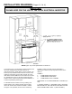
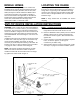
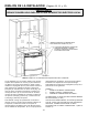
FIGURE 1
NOTE: Figure may not be representative of actual unit.
The 30 inches (76.2 cm) minimum clearance between the
top of the cooking surface and the bottom of an
unprotected wood or metal cabinet can be reduced to 24
inches (61 cm) minimum when bottom of wood or metal
cabinet is protected by not less than 1/4-inch (6.4 mm)
thick flame-retardant millboard covered with not less than
No. 28 MSG sheet steel, 0.015-inch (0.381 mm) thick
stainless steel, 0.024-inch (0.610 mm) thick aluminum, or
0.020-inch (0.508 mm) thick copper.
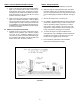
To eliminate the risk of burns or fire by reaching over
heated surface units, cabinet storage space located
above the surface units should be avoided. If cabinet
storage is to be provided, the risk can be reduced by
installing a range hood that projects horizontally a
minimum of 5 inches (13 cm) beyond the bottom of the
cabinets.
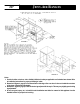
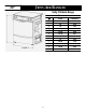
FIGURE 1
1 COMBUSTIBLE BACK WALL....
2 COMBUSTIBLE SIDE WALL....
3 COMBUSTIBLE WALL CABINET....
DIMENSION “A” IS TO BE A MINIMUM OF 3 INCHES (7.5
CM).
A SLIDE-IN RANGE, IF EQUIPPED WITH OPTIONAL
BACKGUARD KIT, MAY BE INSTALLED ZERO INCHES
FROM COMBUSTIBLE WALL 1 (SEE FIGURE 1).