
Installation guide

-6-
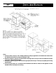
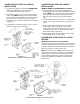
STEP 2 - Anti-Tip Bracket Installation
Options
A. Wood Construction:
1. Floor: Locate the center of thetwo holes identified in
figure 5 as “HOLES FOR FLOOR.” Drill a 1/8² (3
mm) pilot hole in the center of each hole (a nail or
awl may beused if a drillis not available). Securethe
ANTI-TIP bracket to the floor with the two screws
provided. Proceed to STEP 3.
2. Wall: Locate the center of the two holes identified in
figure 5 as “HOLES FOR WALL.” Drill an angled
1/8² (3 mm) pilot hole in the center of each hole as
shown in figure 6. (A nail or awl may be used if a drill
is not available). Securethe ANTI-TIP bracket tothe
wall with the two screws provided as shown in figure
6. Proceed to STEP 3.
B. Cement or Concrete Construction:
1. Suitable screws for concrete construction can be
obtained at the hardware store. Drill the required
size hole for the hardware obtained into the
concrete at the center of the holes identified infigure
5 as “HOLES FOR FLOOR”. Secure the ANTI-TIP
bracket to the floor. Proceed to STEP 3.
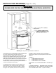
STEP 3 - Range
Installation
A. A Jenn-Air range may be installed by one person.
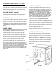
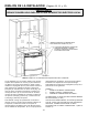
B. Align the range to its designated location and slide it
back into position. Note: A minimum clearance of 1/4²
(6 mm) is required between the range and the leveling
foot that will engage the ANTI-TIP bracket, see figure
6.
C. All Jenn-Air ranges have a non lift-up top.
D. For SAFETY CONSIDERATIONS as well as optimum
performance adjust the range so that it is level. This
may be checked by placing a spirit level or a large
pan of water on the cooktop or the oven rack. If an
adjustment is required pull the range forward, tip the
range and rotate the leveling feet as required.
E. To check the range for proper installation of the
anti-tip bracket: Use a flashlight and look underneath
the bottom of the range to see that one of the rear
leveling feet is engaged in the bracket slot.
F. Proceed with the remainder of the installation
instructions provided with the range.
FIGURE 6