
Owner's Manual

11
Connecting the Drain
After ensuring that the drain system is adequate, follow these
steps to properly place the ice maker:
1. Plug into a grounded 3 prong outlet.
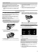
2. Style 1—For gravity drain system, push the ice maker into
position so that the ice maker drain tube is positioned over
the PVC drain reducer. See “Gravity Drain System.”
Style 2—For drain pump system connect the drain pump
outlet hose to the drain. See “Drain Pump System.”
3. Recheck the ice maker to be sure that it is level. See
“Leveling.”
4. If it is required by your local sanitation code, seal the cabinet
to the floor with an approved caulking compound after all
water and electrical connections have been made.
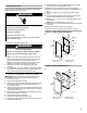
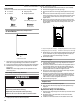
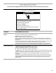
Install Custom Overlay Panel
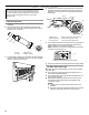
IMPORTANT: Create custom overlay panel according to the
specifications in the “Custom Panel Dimensions” section.
1. Install the ice maker.
2. Level the ice maker. See “Leveling.”
3. Place the ice maker under the cabinet so that the front edge
of the custom panel will align with the front edge of the
surrounding cabinets.
4. Hold the custom panel up to the ice maker and check that the
opening and alignment are correct. Mark location of the panel
on the unit as necessary.
5. Mark location of the handle. Remove the panel from the door,
and then drill holes for the handle.
6. Install the door handle on the panel.
7. Remove the tape from the face of the door.
8. Remove the paper backing from the adhesive pads that are
located on the door front.
9. Place the panel on the door, align with markings and apply
pressure in the area of the adhesive pads.
10. Make sure the ice maker door opens and closes easily.
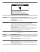
11. Pull the ice maker forward to access the top and sides of the
door.
12. Remove the gaskets from the interior door panel and set
aside.
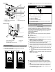
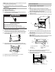
13. Using the factory drilled holes as a guide, use a pencil and
mark the drilling locations on the overlay panel.
14. Drill eight ¹⁄₈" x ¹⁄₂" (3.18 mm x 12.7 mm) deep holes into the
overlay panel.
NOTE: Do not drill deeper than ¹⁄₂" (12.7 mm).
15. Use eight #8 x ¹⁄₂" pan-head wood screws to attach the panel
to the door.
16. Replace the gaskets on the inner door panel.
17. Move the ice maker back into place under the counter.
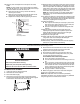
Option 1—Without Hinge-Side Spacer
Option 2—With Hinge-Side Spacer
Electrical Shock Hazard
Plug into a grounded 3 prong outlet.
Do not remove ground prong.
Do not use an adapter.
Do not use an extension cord.
Failure to follow these instructions can result in death,
fire, or electrical shock.
WARNING
WARNING
Excessive Weight Hazard
Use two or more people to move and install ice maker.
Failure to do so can result in back or other injury.
A. #8 x
¹⁄₂
" pan-head
wood screw
B. Adhesive pads
C. Custom panel
A. #8 x
¹⁄₂
" pan-head
wood screw
B. Adhesive pads
C. Custom panel
A
C
B
14¹⁷⁄₃₂"
(36.9 cm)
29
¹⁄₂"
(74.9 cm)
29¹⁄₂"
(74.9 cm)
14⁵⁄₈"
(37.1 cm)
A
C
B