Installation Instructions Over the Range Microwave Oven BEFORE YOU BEGIN Read these instructions • • and carefully. • Note to Consumerfuture reference. • Skill level - Installation of this appliance basic mechanical and electrical skills. and ordinances. • Proper installation installer. Note to InstallerBe sure to leave these instructions with the Consumer. • Product failure due to improper covered under the Warranty.
Installation Instructions CONTENTS General information C Important Safety Instructions Electrical Requirements ..................... 3 .............................. 3 Outside Back Exhaust ............................. Preparing Attach Damage ........................................... - Shipment/Installation 4, 5 ................. 6 Parts Included ............................................... 6 Tools You Will Need ..................................... 7 Mounting 7 Space ........
Installation Instructions IMPORTANT SAFETY INSTRUCTIONS This product requires a three-prong grounded outlet. The installer must perform a ground continuity check on the power outlet box before beginning the installation to insure that the outlet box is properly grounded. If not properly grounded, or if the outlet box does not meet electrical requirements noted (under ELECTRICAL REQUIREMENTS), a qualified electrician should be employed to correct any deficiencies.
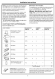
Installation Instructions HOOD EXHAUST NOTE: Read these next two pages only if you plan to vent your exhaust recirculate the air back into the room, proceed to page 11. OUTSIDE TOP EXHAUST (EXAMPLE ONLY) The following ductwork chart describes an example of one possible DUCT PIECES to the outside. If you plan to installation. EQUIVALENT LENGTH x NUMBER USED = EQUIVALENT LENGTH Roof Cap 24 Ft. x (1) = 24 Ft. 12 Ft. Straight Duct (6" Round) 12 Ft. x (1) = 12 Ft. x (1) = 5 Ft.
Installation Instructions NOTE: If you need to install ducts, note that the total duct length of 3¼" x 10" rectangular or 6" diameter round duct should not exceed 60 equivalent feet. Maximum Outside ventilation requires a HOOD DUCT. Read the following carefully. EXHAUST Elbows, transitions, wall and roof caps, etc.
Installation Instructions DAMAGE - SHIPMENT/ INSTALLATION • PARTS INCLUDED HARDWARE If the unit is damaged in shipment, return the unit to the store in which it was bought for repair or replacement. • If the unit is damaged by the customer, or replacement is the responsibility of the customer. • If the unit is damaged by the installer (if other than the customer), repair or replacement must be made by arrangement between customer and installer.
Installation Instructions TOOLS YOU WILL NEED Ruler or tape measure .....
Installation 1.PLACEMENT Instructions OF THE MOUNTING PLATE A. REMOVING THE MICROWAVE OVEN FROM THE CARTON/ REMOVING THE MOUNTING PLATE 1, Remove the installation instructions, B. FINDING THE WALL STUDS Exhaust adaptor, filters, glass tray and the small hardware bag. Do not remove the Styrofoam protecting the front of the oven. 2. Fold back all 4 carton flaps fully against carton sides. Then carefully roll the oven and carton over onto the top side. The oven should be resting in the Styrofoam. 1.
Installation C. DETERMINING Plate position - beneath Instructions WALL PLATE LOCATION UNDER YOUR CABINET flat bottom cabinet Draw a vertical line on the wall at the center of the 30" wide space. Tape the Rear Wall Template onto the wall matching the centeriine and touching the bottom of the cabinet. Plate position - beneath cabinet bottom framed recessed 33" to Cooktop Draw a vertical line on the wall at the center of the 30" space.
Installation D. ALIGNING Instructions THE WALL PLATE i i REAR WALk TEMPLATE _;:_,,_!_: ........................ Centedine notches __ Draw a Vertical Line on Wall from Center _<___ of Top Cabinet o I'''- Horizontal Line o o o o o o o o o 7 Area E Hole C Hole B Horizontal Draw a Horizontal Line line on wall from bottom of "Rear Wall Template". CAUTION: Wear gloves to avoid cutting fingers on sharp edges.
Installation 2. INSTALLATION TYPES This microwave oven is designed for adaptation the following three types of ventilation: A. Recirculating (Non-Vented B. Outside Top Exhaust C. Outside Back Exhaust Instructions (Choose A, B or C) to NOTE: This microwave is shipped after being assembled for "Recirculating". And exhaust adaptor is shipped assembled to the filler-upper. Select the type of ventilation required for your installation and proceed to that section.
Installation A. RECIRCULATING (Non-Vented INSTALLATION OVERVIEW A1. Attach Plate to Wall Mounting Instructions Ductless) A2. Prepare Top Cabinet A3. Mount the Microwave Oven + AI.__.ATTACH THE MOUNTING TO THE WALL PLATE 3. Place the mounting plate against the wall and insert the toggle wings into the holes in the wall to mount the plate.
Installation MOUNT THE MICROWAVE Instructions OVEN especially cabinet. when mounting flush to bottom of Cabinet Front Cabinet Bottom Shelf Filler Block T Equivalent to Depth of FOR EASIER SAFETY, INSTALL INSTALLATION WE RECOMMEND THIS MICROWAVE IMPORTANT: installation. AND PERSONAL THAT TWO OVEN. Cabinet Recess PEOPLE igning Screw Do not grip or use handle during Microwave NOTE: If your cabinet is metal, use the nylon grommet around the power cord hole to prevent cutting of the cord. 4.
Installation B. OUTSIDE TOP EXHAUST INSTALLATION OVERVIEW B1. Attach Plate to Walt Mounting Instructions (Vertical Duct) B2. Prepare Top Cabinet B3. Adjust Blower B4. Check Damper Operation B5. Mount Microwave B6. Adjust Exhaust B7.
Installation Instructions B2. USE TOP CABINET TEMPLATE FOR PREPARATION OF TOP CABINET B3. ADAPTING MICROWAVE BLOWER FOR OUTSIDE TOP EXHAUST 1. Remove You need to drill holes for the top support screws, a hole large enough for the power cord to fit through, and a cutout barge enough for the exhaust adaptor. and save 2. screw that holds Lift up the blower plate. blower plate to microwave. Biower Piate Back of Microwave Screw 3. • Read the instructions TEMPLATE.
Installation Instructions B5.__. MOUNT THE MICROWAVE FOR EASIER SAFETY, INSTALL 5. Place the blower WE RECOMMEND THIS MICROWAVE IMPORTANT: installation. unit back into the opening. INSTALLATION OVEN AND PERSONAL THAT TWO PEOPLE OVEN. Do not grip or use handle during NOTE: If your cabinet is metal, use the nylon grommet around the power cord hole to prevent cutting of the cord. NOTE: We recommend using filler blocks if the cabinet front hangs below the cabinet bottom shelf.
Installation B5.__.. MOUNT THE MICROWAVE Instructions OVEN B6. ADJUST THE EXHAUST ADAPTOR (cont.) Open the top cabinet and adjust the exhaust to connect to the house duct. Cabinet Front Cabinet Bottom Shelf Back of Blower-Plate Filler Block Damper Microwave Depth of Cabinet Equivalent to Recess ._ Seif-Aligning For Front-to-Back Screw Adjustment, Slide the Exhaust Adaptor as Needed Microwave Oven Top 4, Attach the microwave adaptor oven to the top cabinet. 5.
Installation C, OUTSIDE BACK EXHAUST INSTALLATION C1. Prepare C2. Attach Instructions (Horizontal Duct) OVERVIEW Rear Wall Mounting Plate to Wall | C3. Prepare Top Cabinet C4. Adjust Blower C5. Mount the Microwave Oven Clm PREPARING THE REAR WALL FOR OUTSIDE BACK EXHAUST You need to cut an opening in the rearwall exhaust. C2m ATTACH THE MOUNTING TO THE WALL PLATE for outside Attach the plate to the wall using toggle bolts.
Installation C2.__.. ATTACH THE MOUNTING TO THE WALL (cont.) Instructions PLATE C4. ADAPTING MICROWAVE BLOWER FOR OUTSIDE BACK EXHAUST 1, Remove To use toggle bolts" and save screw that holds btower Plate to microwave. Spacing for Toggles More Than Wall Thickness Blower motor screw. I Toggle Wings 2, Mounting Plate Lift up the Blower Plate. Blower Motor Back of Microwave Belt End "_'_r..... Blower Motor Screw 3.
Installation 6. Place the blower Instructions C5. MOUNT THE MICROWAVE unit back into the opening. OVEN End A End B FOR EASIER SAFETY, INSTALL CAUTION: Do not pull or stretch the blower unit wiring. Make sure the wires are not pinched. NOTE: The blower unit exhaust openings should match exhaust openings on rear of microwave oven. 7, Secure the blower unit to the microwave WE RECOMMEND THIS MICROWAVE IMPORTANT: installation.
Installation C5.__.MOUNT THE MICROWAVE Instructions OVEN (cont.) Install grease filters. See the Owner's with the microwave. Manual packed Cabinet Front Cabinet Bottom Shelf Filler Block -_ Depth of Cabinet Recess Equivalent to gning Screw Microwave Oven Top 4. Attach the microwave oven to the top cabinet. 5, Insert 2 self-aligning screws through outer top cabinet holes. Turn two full turns on each screw. I lighten center screw completely. 7.
Installation Instructions BEFORE YOU USE YOUR MICROWAVE 1, Make sure the microwave installed according 2, Remove all packing 6. oven has been material 7, KEEP INSTALLATION from the microwave THE LOCAL 3. Install turntable electrical and ring in cavity. house fuse or turn breaker 5, Plug power Manual. to instructions. oven. 4. Replace Read the Owner's cord into a dedicated back on. 20 amp outlet. 22 INSTRUCTIONS INSPECTOR'S USE.
Installation Instructions NOTE 23
Part No. : 8101 P710-60 Form No. : Code No.
Instructions d'installation Four _ micro-ondes plus grand que la normale AVANT DE COMMENCER Veuillez lire attentivement et dans leur int_gralit_ les instructions suivantes. • IMPORTANT -- Conservez en vue de leur utilisation • IMPORTANTregtementation • • Remarque & I'attention du consommateurVeuillez conserver ces instructions en vue d'une utilisation future. • Niveau ces instructions par un contr61eur local. Respectezla en vigueur.
Instructions d'installation TABLE DES MATIERES Gdndralit s C Importantes Normes consignes electriques de securit_ ...................................... Evacuation ................................................ Dommages - Transport/Installation Pi_ces Outils fournies Manuel d'installation dtape Positionnement de Retrait de la plaque de montage des montants Positionnement Alignement Types A de la plaque murale .............. ..............................
Instructions d'installation IMPORTANTES CONSIGNES DE SECURITE Le cordon Ce produit dolt 6tre branche a une prise secteur & fiche tripolaire mise a la terre. L'instaltateur dolt verifier la continuite de la mise a la terre au niveau de de ce produit est _quipd d'une prise & fiche tripolaire (mise & la terre) qui doit _tre branch_e la prise murale avant de commencer I'installation afin de s'assurer que la prise est correctement mise a la terre.
Instructions d'installation EVACUATION REMARQUE : Lisez ces deux pages uniquement vous envisagez de r_injecter I'air dans la piece, EVACUATION Le schema suivant EXTERIEURE constitue PAR LE HAUT (EXEMPLE un exemple COMPOSITION d'installation DES CONDUITS Chapiteau (toit) Conduit droit de 12 pieds (diametre m m si vous envisagez une _vacuation passez & la page 11. vers I'ext_rieur. Si UNIQUEMENT) du reseau de gaines.
Instructions REMARQUE : Si vous 6tes amene d'installation & installer des Longueur maximale du conduit • tuyaux, notez que la Iongueur totale du conduit rectangulaire de 3¼" x 10" ou du conduit de 6" de diametre ne dolt pas exceder un equivalent de 60 pieds Pour la bonne circulation de Fair, la longueur totate du conduit rectangulaire de 3¼" x 10" ou du conduit de 6" de diametre ne doit pas exceder un equivalent de 60 pieds. Toute ventilation D'EVACUATION.
Instructions mouvement d'installation PIECES FOURNIES d'un raccord rectangutaire-circulaire, *les IMPORTANT : Enducas d'utilisation coins inferieurs registre doivent 6tre ajustes & I'aide des petites cisaitles & tele pour permettre le fibre du registre. QUlNCAILLERIE PIECE QUANTITE Les Iongueurs equivalentes de ces pieces ont 6te calcutees d'apres des test reels pour une bonne ventilation quel que soit le modete de hotte utilise.
Instructions d'installation OUTILS NECESSAIRES Regle ou galon et e de precision Toumevis Crayon Phillips n ° 1 et 2 Cisailles a tSie (pour decouper le registre, au besoin) Gants Lunettes de protection Ciseaux (pour decouper ie gabarit, au besoin) Perceuse electrique avec meches de 3/16", _/2" et de 5/8" CaIes ou morceaux de bois inserer entre le four et Q i'armoire superieure si necessaire (utilise dans le cas d'installations sous des armoires encastrees uniquement) Scie (scie sauteuse, scie-cl
Instructions 1.POSITIONNEMENT d'installation DE LA PLAQUE DE MONTAGE A. DEBALLAGE DU FOUR A MICRO-ONDES/DE LA PLAQUE DE MONTAGE 1. Sortez les instructions d'instaltation, d'evacuation, les filtres, le plateau petit sac de pieces de quincaillerie. le polystyrene expanse protegeant B. RECHERCHE DU MUR DES MONTANTS I'adaptateur en verre et le N'enlevez pas I'avant du four. ' i ' i¢"_/ _ - 4ontants du mut 2. Repliez completement les 4 rabats contre les parois du carton.
Instructions C. POSITIONNEMENT Emplacement lisse d'installation DE LA PLAQUE MURALE SOUS L'ARMOIRE de la plaque - Sous une armoire Tracez une ligne verticale sur lemur au centre de I'espace de 30" de large. Scotchez le gabarit pour lemur arriere sur lemur correspondant a I'axe et etant en contact avec la base de I'armoire.
Instructions D. ALIGNEMENT d'installation DE LA PLAQUE MURALE i i REAR WALL TEMPLATE _;:{,,_!_ : ........................ Encoches Tracez une li.qneverticale sur,lemur pa_ant du centre au niveau de I'axe __==_=_ o Ligne horizontale ae i'armolre superleure o o o l'espace 2. Tracez "gabarit o o o sur lemur au centre de une ligne verticate sur lemur a la base du o Trou B Ligne horizontale une ligne horizontate sur lemur partant de la base du "gabarit pour lemur arriere".
Instructions 2. TYPES D'INSTALLATION d'installation (Choisissez Ce four a micro-ondes s'adapte sur les trois systemes de ventilation suivants : A. Recyclage de rair non ventild) B. Evacuation (syst_me REMARQUE : Ce four a micro-ondes est exp6die monte pour "Recyclage de Fair". Un raccord de ventilation est foumi : il est fixe a I'appareil. Choisissez le type de ventilation requis pour votre installation et reportez-vous & la section correspondante.
Instructions A. RECYCLAGE PRESENTATION L'INSTALLATION DE L'AIR (syst_me sans conduit non ventild) DE A1. Fixez la plaque de montage A2.Preparez l'armoire A3. Montez d'installation au mur superieure le four & micro-ondes i______________|||_______________|||_______________|||_______________|||_______________|||_______________|||_______________|||_______________|||_______________|||_______________|||_______________|||_______________|||_______________|||_______________|||_______________|||____I AI.
Instructions MONTEZ ONDES d'installation LE FOUR A MICRO- plus particuli_rement Iorsque vous four avec le fond de I'armoire. alignez le Fa£ade de I'armoire Fond de I'armoire Cale profondeur du renfoncement de quivalent de la I'armoire I POUR UNE PLUS GRANDE SIMPLICITE D'INSTALLATION ET POUR VOTRE PROPRE SECURITE, IL EST RECOMMANDE POUR INSTALLER CE PRODUIT. D'ETRE Visa DEUX Haut du four a micro-ondes IMPORTANT : N'utilisez pas de griffe de levage ni de poign_e au cours de rinstallation.
Instructions B, EVACUATION PRESENTATION L'INSTALLATION EXTERIEURE B3. PAR LE HAUT (conduit vertical) DE B1. Fixez la plaque de montage B2. Preparez d'installation I'armoire au mur su )erieure Reglez le ventilateur | B4. Test du registre B5. Montez le four a micro-ondes B6. Reglez I'adaptateur B7.
Instructions d'installation B2.m.. UTILISEZ LE GABARIT DE L'ARMOIRE SUPERIEURE POUR PREPARER CETTE ARMOIRE B3. ADAPTATION DU VENTILATEUR DU FOURA MICRO-ONDES POUR UNE EVACUATION EXTERIEURE PAR LE HAUT Vous devrez percer des trous pour les vis soutenant le haut du four, un trou suffisamment large pour le passage du cordon d'alimentation et une ouverture suffisante pour I'adaptateur d'evacuation. 1. Retirez 2. Soulevez la vis qui soutient la plaque du ventilateur dans le four & microondes.
Instructions d'installation MONTEZ ONDES LE FOUR A MICRO- POUR UNE PLUS GRANDE 5. Reptacez le ventilateur SIMPLICITE D'INSTALLATION ET POUR VOTRE SECURITE, EST RECOMMANDE D'ETRE DEUX POUR INSTALLER CE PRODUIT. dans I'ouverture. IL IMPORTANT : N'utilisez pas de griffe de levage ni de poign_e au cours de I'installation. REMARQUE : Si votre armoire est metatlique, ptacez le guide en nylon autour du trou prevu pour le passage du cordon d'alimentation pour que ce dernier ne se coupe pas.
Instructions d'installation ONDES (suite) B6. REGLEZ L'ADAPTATEUR D'EVACUATION Facade de I'armoire Fond de I'armoire Ouvrez I'armoire superieure et reglez I'adaptateur d'evacuation pour le brancher au conduit. Cale Arriere du four Piaque du ventilateur Registre a micro-ondes profondeur du renfoncement de quivalent de la I'armoire I Visa autoreglage Haut du four a micro-ondes 4.
Instructions C, EVACUATION EXTERIEURE PRESENTATION L'INSTALLATION Cl. Preparez lemur PAR L'ARRIERE (Conduit horizontal) DE arriere C2. Fixez la plaque de montage C3.Preparez d'installation I'armoire au mur superieure C4. Reglez le ventilateur C5. Montez le four a micro-ondes C1. PREPARATION DU MURARRIERE POUR UNE EVACUATION EXTERIEURE PAR L'ARRIERE C2._.FIXEZ LA PLAQUE AU MUR DE MONTAGE Vous devez percer une ouverture dans le mur arriere pour permettre I'evacuation vers I'exterieur.
Instructions d'installation C2.__.FIXEZ LA PLAQUE DE MONTAGE AU MUR (suite) Pour utiliser les boulons C4. ADAPTATION DU VENTILATEUR DU FOUR A MICRO-ONDES POUR UNE EVACUATION EXTERIEURE PAR L'ARRIERE a ailette • Espace necessaire aux boulons , sup@ieur a I'epaisseur du mur 1. Retirez et conservez la vis qui soutient ta plaque du ventitateur dans le four a micro-ondes. ! Ailettes = Plaque de 2, Soulevez la plaque du ventitateur. Vis du moteur du ventilateur.
Instructions 6. Reptacez le ventilateur d'installation C5. MONTEZ ONDES darts I'ouverture. LE FOUR A MICRO- Extremit6 A Extremit6 B POUR UNE PLUS GRANDE SIMPLICITE D'INSTALLATION ET POUR VOTRE PROPRE ATTENTION : Ne tirez pas sur les ills du ventilateur. Veillez & ne pas pincer les ills. REMARQUE : Les ouvertures du ventilateur SECURITE, IL EST RECOMMANDE POUR INSTALLER CE PRODUIT. pr_vues pour I'_vacuation doivent cofncider avec celles qui se trouvent & I'arri_re du four & microondes. 7.
Instructions C5.__.MONTEZ d'installation LE FOUR A MICRO- ONDES (suite) Instatlez les filtres a graisse. Reportez-vous au manuel d'utilisation livre avec le four & micro-ondes. Fa£ade de I'armoire Fond de I'armoire Cale profondeur du renfoncement Equivalent de de la I'armoire Haut du four a micro-ondes 4. Fixez le four & micro-ondes a I'armoire superieure. 5. Inserez 2 visa autoreglage dans les trous exterieurs effectues sur I'armoire superieure. Vissez chaque vis en effectuant deux tours complets.
Instructions d'installation AVANT D'UTILISER VOTRE FOUR A MICRO-ONDES 6, 1. Verifiez que le four a micro-ondes a et6 installe conformement aux instructions fournies. Consultez le manuel 7, CONSERVEZ 2, Enlevez tousles I'interieur du four. materiaux 3, guidage. Instatlez 4. le plateau Replacez tournant d'embatlage et I'anneau ptaces & de les fusibtes ou remettez le disjoncteur le cordon & une prise I I en marche. 5, Branchez electrique d'alimentation de 20 A (prise dedi6e).
Instructions d'installation REMARQUE 23
Ref6rence : 8101 P710-60 N° formulaire :A/08/05 Code n ° : DE68-03141B
Instrucciones de instalacibn Para toda la gama de hornos microondas ANTES DE EMPEZAR Lea estas instrucciones detenidamente • IMPORTANTE: para referencia • • y Guarde estas instrucciones det inspector IMPORTANTE: normativas completa • Nota para el usuario: Guarde estas instrucciones para posteriores consultas. • Capacitacibn: requiere conocimientos mecanica. local. Tenga en cuenta todas las locales. Nota para el instalador: AsegQrese de que el usuario se quede con estas instrucciones.
Instrucciones de instalacibn INDICE GENERAL Informacion Instrucciones Requisitos Difusor general importantes electricos de escape .... 3 3 .................................... - Envio/Instalaci6n Piezas incluidas Espacio sobre seguridad ................................... Da_os Herramientas C 4, 5 ........................... ............................................ que necesitara para el montaje ...................... ..............................
Instrucciones INSTRUCCIONES de instalacibn DE SEGURIDAD IMPORTANTES Un electricista cualificado debe Este producto necesita un enchufe mural con toma a tierra de tres patas. El instalador debe realizar una prueba de continuidad de la puesta a tierra en ta toma de corriente antes de comenzar la instalaci6n, para asegurarse de que et enchufe este correctamente conectado a tierra.
Instrucciones de instalacibn DIFUSOR DE ESCAPE NOTA: Lea las dos p&ginas siguientes sblo si desea que el escape de ventilacibn desea que recircule el aire de nuevo hacia la habitacibn, consulte la p&gina 11. ESCAPE SUPERIOR AL EXTERIOR El diagrama siguiente describe un ejemplo (EJEMPLO) de una posible PIEZAS DE CONDUCCION instalaci6n de conducciones.
Instrucciones de instalacibn Si se necesita NOTA: Si necesita instalar conducciones, tenga en cuenta que la longitud total de la conducci6n rectangular de 8,25 x 25,40 cm o la conducci6n redonda de 15,24 cm no debe superar los 18,29 metros equivalentes. Longitud no debe superar NOTA: Es importante la instalaci6n de la ventitaci6n siga la ruta mas directa y tenga los menos codos posibles. De este modo se asegura una salida despejada del escape y se previenen tas obstrucciones.
Instrucciones de instalacibn PIEZAS INCLUIDAS adaptador de transici6n de ectangular *a IMPORTANTE: Si se utiliza un del redondo, las esquinas inferiores regulador de tiro se deberan cortar para conseguir el ajuste, usando la cortadora, con et fin de permitir el libre movimiento del regulador de tiro.
Instrucciones HERRAMIENTAS de instalacibn QUE NECESITARA Regla o cinta metrica y e recto Destorniliador Phillips # 1 y # 2 Lapiz (opcional) Cortadora (para cortar el regulador de tiro, si fuera necesario) Taladro electrico con brocas Tijeras (para cortar la plantilla, si fuera necesario) de 3/16", _/2"y 5/8" Bloques de relleno 0 trozos de madera, si fuera necesario para el espacio del armario superior (solamente para instalaciones empotradas de ia parte inferior) Guantes Gafas de seguridad
Instrucciones I.COLOCACION de instalacibn DE LA PLACA DE MONTAJE A. EXTRACClON DEL MICROONDAS DE LA CAJA/ EXTRACCION DE LA PLACA DE MONTAJE 1. Saque las instrucciones de instalaci6n, B. BUSQUEDA DEL ENTRAMADO DE LA PARED el adaptador det escape, los filtros, la bandeja de cristal y la pequefia bolsa con piezas. No retire la protecci6n de poliestireno del frontal det homo. 2. Doble las cuatro sotapas de la caja hacia los laterates.
Instrucciones C. UBICACION de instalacibn DE LA PLACA MURAL BAJO EL ARMARIO Posicibn de la placa: bajo el armario superficie inferior lisa de Posicibn armario de la placa: bajo la parte inferior del empotrado t I _L ii Trace una linea vertical I en la pared, en el centro AI menos a 76,2 cm de un espacio 83,8 cm hasta el piano de cocci6n de 76,2 cm de ancho. Pegue la plantitta posterior en la pared, haciendola coincidir con la tinea central y tocando el borde inferior del armario.
Instrucciones D. ALINEACION de instalacibn DE LA PLACA MURAL i i REAR WAL t TEMPLATE i Orificio A Ranuras de I& Trace una linea vertical linea central i en,la pare.ddesde,el centrc __ _.._e-- ael armano supenor o Linea horizontal o o Orificio C o o o o o o o Orificio B Linea horizontal Trace una linea horizontal pared desde la parte inferior de la "Plantitla posterior para la pared". PRECAUCION: P6ngase guantes para evitar cortarse los dedos con los bordes afilados. 1.
Instrucciones 2. TIPOS DE INSTALACION El microondas esta disefiado para adaptarlo tres tipos de ventitaci6n siguientes: A. Recirculacibn (sin conducciones de instalacibn (Seleccione a los NOTA: Este microondas se suministra preparado para ta "Recirculaci6n". Se suministra el adaptador de escape montado en et relleno superior. Seleccione el tipo de ventilaci6n requerido para la instataci6n y continL_e con esa secci6n. de ventilacibn) B.
Instrucciones A. RECIRCULACION VISION GENERAL INSTALAClON A1. Acople A3.Monte (sin conducciones de ventilacibn) DE LA la placa de montaje A2. Prepare el armario de instalacibn a la pared i superior el microondas AI.__.FIJE LA PLACA DE MONTAJE LA PARED A 3. Coloque la placa de montaje inserte las patomiltas en los orificios para montar la placa.
Instrucciones de instalacibn A3m MONTE EL MICROONDAS Frontal dei armario Estante inferior del armario Je de reileno Equivalente a la profundidad del armario empotrado PARA FACILITAR LA INSTALACION Y MEJORAR Tornillo de autoalineacion LA SEGURIDAD, SE RECOMIENDA QUE EN LA INSTALAClON DE ESTE MICROONDAS PARTIClPEN DOS PERSONAS. IMPORTANTE: No sujete durante la instalacibn.
Instrucciones B. ESCAPE SUPERIOR VISION GENERAL INSTALAClON B1. Acople B2. AL EXTERIOR (Conduccibn vertical) DE LA la placa de montaje Prepare el armario de instalacibn a la pared superior B3. Ajuste el ventilador B4. Compruebe el funcionamiento regulador de tiro det i B5. Monte el microondas B6. Ajuste et adaptador B7.
Instrucciones de instalacibn B3. ADAPTACION DEL VENTILADOR DEL MICROONDAS AL ESCAPE EXTERIOR SUPERIOR B2.__.USE LA PLANTILLA DEL ARMARIO SUPERIOR PARA PREPARARLO 1. Retire Debe taladrar orificios para los tornillos superiores de soporte y un orificio Io suficientemente grande para pasar por et el cable de alimentaci6n, asi como un corte lo suficientemente grande para el adaptador de escape. 2. Levante et tornillo que sostiene la placa del ventilador al microondas la placa del y guardelo>.....
Instrucciones de instalacibn B5.__. MONTE EL MICROONDAS PARA FACILITAR 5, Vuetva a colocar et ventilador en la abertura. LA INSTALACl0N Y MEJORAR LA SEGURIDAD, SE RECOMIENDA QUE EN LA INSTALACl0N DE ESTE MICROONDAS PARTIClPEN DOS PERSONAS. IMPORTANTE: No sujete el horno por las asas durante la instalacibn. NOTA: Si el armario es metatico, proteja el orificio del cable de atimentaci6n con arandelas de nylon para evitar que este se pueda cortar. / PRECAUCION:No saque ni tire de los cables.
Instrucciones de instalacibn B5.m.. MONTE EL MICROONDAS B6. AJUSTE EL ADAPTADOR ESCAPE (continuacibn) Abra et armario superior y ajuste el adaptador de escape para conectarlo a la conducci6n de la casa. Frontal del armario Estante inferior del armario Placa del ventilador Bloque de reileno __ DE Equivalente profundidad Regulador de tiro Parte posterior del microondas a la del armario empotrado Tomillo de autoalineacion adaptader de escape segun se necesite Parte superior del microondas 4.
Instrucciones C. ESCAPE POSTERIOR VISION GENERAL INSTALAClON Cl.Prepare C2. Acople de instalacibn AL EXTERIOR (Conduccibn horizontal) DE LA la pared posterior la ptaca de montaje a la pared C3. Prepare el armario C4.Ajuste et ventilador C5.Monte el microondas superior i Clm PREPARACION DE LA PARED POSTERIOR PARA EL ESCAPE POSTERIOR AL EXTERIOR Debe cortar una abertura el escape al exterior.
Instrucciones de instalacibn 04. ADAPTACION DEL VENTILADOR DEL MICROONDAS AL ESCAPE EXTERIOR POSTERIOR C2.m.. FIJE LA PLACA DE MONTAJE A LA PARED (continuacibn) Para usar los pernos acodados" 1. Retire Procurar un espacio para los pernos acodados superior aJgrosor de la pared [ et tornilto que sostiene ventilador al microondas la ptaca del y guardeto. ! PalomilJas Placa de = Tornillodel motor del ventiJador. 2, montaje Levante la placa del ventitador.
Instrucciones _ro Despuesdel de instalacibn Empuje con firmeza hasta que Ilegue a las pestafias inferiores de cierre. AsegQrese de que ta bisagra del regulador de tiro este instalada en la parte superior y que et regutador gire con facitidad. giro C5. MONTE EL MICROONDAS a I Parte posterior dei microondas Parte posterior del microondas 6, Vuetva a colocar et ventilador en la abertura.
Instrucciones de instalacibn C5.m.. MONTE EL MICROONDAS (continuacibn) Instate los filtros de grasa. Consulte el manual usuario que se suministra con el microondas. del Frontal del armario Estante inferior del armario Bloque de relleno profundidad armano Equivalente empotrado deI a la autoalineacion Parte superior dei microondas 4. Fije el microondas al armario 5, Inserte dos tornillos superior. de autoatineaci6n a traves de los orificios exteriores superiores del armario.
Instrucciones de instalacibn ANTES DE UTILIZAR EL MICROONDAS 1. Compruebe de acuerdo 2. microondas. Retire todo el material 3. Instale et plato giratorio 4. Conecte 6, Lea el manual que el microondas se haya instalado con las instrucciones. de embalaje det interior del y el aro en la cavidad. la caja de fusibles I I o vuetva a activarla. m 5, Enchufe et cable de alimentaci6n electrica especifica a una toma de 20 amperios.
Instrucciones de instalacibn NOTA 23
N._ pieza : 8101 P710-60 Formulario : A/08/05 N.