
Installation guide


8
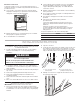
4. Remove the tape from the black front trims and remove the
zip tie from the mounting spacer.
■ Securely fasten the oven to the cabinet using the
#8-14 x 1" (2.5 cm) screws provided.
■ Insert screws through the holes in the black trim aligning
with the holes in the oven frame and mounting spacers
already in place. Do not overtighten screws.
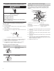
5. The bottom vent is shipped in the foam packing at the top of
the oven. Install the bottom vent (C) as follows:
■ Align vent tab (B) with oven frame (A) as shown.
■ Using one #8-18 x 3/8" (9.5 mm) screw (D) on each side
of the vent tab (B), fasten the vent securely to the oven.
6. Replace oven racks.
7. Replace the oven door. See the “Replace Oven Door(s)”
section.
8. Check that door is free to open and close. If it is not, repeat
the removal and installation procedures. See
“Prepare Built-In Microwave/Oven Combination” section.
9. Reconnect power.
10. The display panel will light briey, and “PF” should appear in
the display.
11. If the display panel does not light, please reference
the “Warranty.”
Install Warming Drawer Deflector
Kit (Only for Ovens Installed
Above Warming Drawers)
On combo microwave/oven models installed above a warming
drawer, a warming drawer deector kit must be installed.
See the “Tools and Parts” section for ordering information.
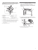
Parts Supplied
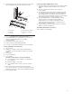
Install Deflector Kit
1. Align the deector (B) with the vent (C) as shown.
2. Using two #8-18 x 1/4" (6.4 mm) screws (A) on each side of
the deector (B), fasten the deector securely to the vent.
NOTE: On 27" (68.6 cm) models, only one #8-18 x 1/4"
(6.4mm) screw is used on each side.
3. Align vent tab (B) with oven frame (A) as shown.
A. Oven frame
B. Mounting spacer
C. Oven frame hole
D. Black trim piece
A
C
D
B
B
A
C
D
B
A. Oven frame
B. Vent tab
C. Oven vent
D. #8-18 x 3/8"
(9.5 mm) screws
B
A
A. Phillips head screws (4)
only 2 screws for 27" (68.6 cm) size
B. Warming drawer deflector (1)
A. #8-18 x 1/4" (6.4 mm) screws
B. Warming drawer deflector
C. Vent
B
A
C
B
C