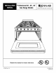
Professional48",36", 30" _ JENN-AIR Gas RangeModels ,03WEST,OO,T. ST°EE,,,ORT...E_O @ @ O @ 0= [J Retain this manual for future (17663 Rev. B) reference.
30'i GAS RANGE MODEL 36" GAS RANGE MODEL MODEL PRG3010 MODEL PRG3610 / ! // \ MODEL PRG4810
TABLE OF CONTENTS MODEL IDENTIFICATION WARNING INTRODUCTION ........................ ...................................... INTRODUCTION IMPORTANT 3 ................................. INSTALLATION STEP 2 - Cabinet Preparation ................ 4 4 5-6 Unpacking, Moving And Placing The Range .......................... 7-8 ANTI-TIP INSTALLATION ....................... 8 INSTRUCTIONS Electrical Connections STEP 5 - Gas Requirements .........
IMPORTANTINSTALLATIONINSTRUCTIONS Tested in accordance with ANSI Z21.1-1993 Standard for Household Cooking Gas Appliances. These ranges must be installed in conjunction with a suitable overhead vent hood. (See Step: 1 for Ventilation Requirements). Due to the professional high heat capacity of this unit, particular attention should be paid to the hood and duct work installation to assure it meets local building codes.
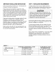
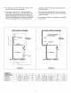
STEP 2: CABINETPREPARATION 1. The range is a free-standing unit. If the unit is to be placed adjacent to cabinets, the clearances shown in Figures 2A/B/C are required. The same clearances apply to island installations. 2. The range can be placed in various positions with respect to the cabinet front, with the front either flush or projecting, depending on the countertop depth. See Figure 3A/B and Table 2 (side view of range) for dimensions. 3.
5. Any openings in the wall behind the range and in the floor under the range must be sealed. 6. When there is less than a 12" clearance between combustible material and the back edge of the range, (above the cooking surface) Jenn-Air Stub Back or High Shelf Backguard must be installed. These parts must be ordered separately, except for the PRG3010 which comes equipped with a Low Back. Figure 3A _\k\\\" ,\\\\\k\' and Figure 3B indicate the space required for each type of backguard. 7.
STEP 3: UNPACKING,MOVING AND PLACING THE RANGE CAUTION PROPER EQUIPMENT AND ADEQUATE MANPOWER MUST BE USED IN MOVING THE RANGE TO AVOID DAMAGE TO THE UNIT OR THE FLOOR. THE UNIT IS HEAVY AND RESTS ON ADJUSTABLE STEEL LEGS. DO NOT LIFT THE RANGE BY THE OVEN DOOR HANDLES!! The 36" range has a shipping weight of approximately 408 pounds or 354 pounds after removal of packing materials.
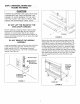
To remove the door, open the door and hold it all the way open. Close the hinge latches (see Figure 8) and release the door. The door can then be removed by gently lifting and pulling the door, with the hinges up and out of the frame. The hinges are assembled to the door and will be removed from the frame when the door is lifted upward. It is important that the two screws retaining the kick panel are secure to prevent accidental access to live electrical components and wires (see Figure 5).
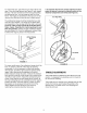
ANTI.TIPDEVICE INSTALLATION NOTE: A risk of range tip over exists if the appliance is not installed in accordance with the installation instructions provided. The proper use of this device minimizes the risk of TIP-OVER. In using the device the consumer must still observe the safety precautions as stated in the USE and CARE MANUAL and avoid using the oven door and/or kick plate as a step stool. Installation instructions are provided for wood and cement in either floor or wall.
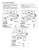
STEP4: ELECTRICAL CONNECTIONS STEP 5: GAS REQUIREMENTS Power Requirements Verify the type of gas supplied to the location. 120 VAC, 60 Hz., single phase. The range is shipped from the factory set up and adjusted for natural gas or LP gas (propane), depending on model ordered. PRG3010PRG3610PRG4810- 4 Amp. Max. 7 Amp. Max. 13 Amp. Max. Natural (Use 15 Amp. Circuit) Always disconnect electric supply cord from the wall outlet or service disconnect before servicing this appliance.
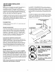
STEP 6: BACKGUARDINSTALLATION Oven and Griddle The backguard must be installed when there is less than a 12" clearance between combustibles and the back of the range above the cooking surface (see Figure 3B). RANGE BACKGUARD HIGH SHELF: (22") LOW SHELF: (12") KITS PRAG3022 - 30" PRAG362236" PRAG4822 - 48" PRAG3612 PRAG4812 Burners Check for the proper burner flame characteristics and adjust air shutters if necessary (see figures 13 - 14).
Surface Burners INSTALLERFINAL CHECK LIST The surface burners are not adjustable. Proper operation is achieved when the correct orifices for the gas supply are installed at the factory, based on model ordered. * If the top burner does not ignite, check the spark igniter by listening for a clicking sound. If you do not hear the igniter click, turn off the burner. Check for a tripped circuit breaker, blown fuse, or poor wire connection to the igniter. _] Placement of unit.
ii !! ct_ _m ct_ 0 _m 0 L_ L_ L_ _m O z c_ Qu
"13 Z o 01 03 0 0 03 < c) LR RF RR A4_:E LR RF RR
SERV[CE BK ) e L i l LIO_I I 2 _ 6 OUAL 42 VN I0 -i.-- IN7 IN IN 17 GN I ON r_ 4_ u2 L0 o D (1) r_ O -i.-O u") (D (D -i.
-u z o 01 O_ o 0 0 7O (D o
Z o 0_ c_ C_
q3 Z o S 03 o 0 CO < o i_ _ ii_ _¸¸¸ _ i_¸¸ _