
Installation Instructions

3
INSTALLATION REQUIREMENTS
Tools and Parts
Gather the required tools and parts before starting installation.
Read and follow the instructions provided with any tools listed
here.
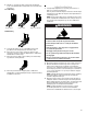
Tools Needed
Parts Supplied
Check that all parts are included.
■ #10 x 1⁵⁄₈" (4.1 cm) screws (for mounting anti-tip bracket) (2)
■ Anti-tip bracket (inside oven cavity)
Anti-tip bracket must be securely mounted to the back wall or
floor. Thickness of flooring may require longer screws to
anchor bracket to subfloor. Longer screws are available from
your local hardware store.
■ Oven racks (3)
Optional Parts
To purchase these or any other accessories, please reference the
“Accessories” section of the User Guide for contact information.
■ Side Trim Kits:
⁵⁄₈" (1.7 cm) White - Order Part Number W10675027
⁵⁄₈" (1.7 cm) Black - Order Part Number W10675026
⁵⁄₈" (1.7 cm) Stainless Steel - Order Part Number W10675028
1¹⁄₈" (2.9 cm) White - Order Part Number W10731885
1¹⁄₈" (2.9 cm) Black - Order Part Number W10731886
1¹⁄₈" (2.9 cm) Stainless Steel - Order Part Number
W10731887
■ Backsplash Kits:
High 6" (15.2 cm) White - Order Part Number W10655448
High 6" (15.2 cm) Black - Order Part Number W10655449
High 6" (15.2 cm) Stainless Steel - Order Part Number
W10655450
Location Requirements
IMPORTANT: Observe all governing codes and ordinances.
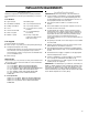
■ It is the installer’s responsibility to comply with installation
clearances specified on the model/serial/rating plate. The
model/serial/rating plate is located behind the oven door on
the top right-hand side of the oven frame.
■ The range should be located for convenient use in the
kitchen.
■ Recessed installations must provide complete enclosure of
the sides and rear of the range.
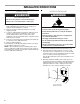
■ To eliminate the risk of burns or fire by reaching over the
heated surface units, cabinet storage space located above
the surface units should be avoided. If cabinet storage is to
be provided, the risk can be reduced by installing a range
hood or microwave hood combination that projects
horizontally a minimum of 5" (12.7 cm) beyond the bottom of
the cabinets.
■ All openings in the wall or floor where range is to be installed
must be sealed.
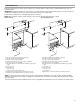
■ Cabinet opening dimensions that are shown must be used.
Given dimensions are minimum clearances.
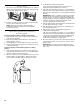
■ The anti-tip bracket must be installed. To install the anti-tip
bracket shipped with the range, see “Install Anti-Tip Bracket”
section.
■ Grounded electrical supply is required. See the appropriate
“Electrical Requirements” section.
■ Contact a qualified floor covering installer to check that the
floor covering can withstand at least 200°F (93°C).
■ Use an insulated pad or ¼" (0.64 cm) plywood under range if
installing range over carpeting.
IMPORTANT: To avoid damage to your cabinets, check with your
builder or cabinet supplier to make sure that the materials used
will not discolor, delaminate or sustain other damage. This oven
has been designed in accordance with the requirements of UL
and CSA International and complies with the maximum allowable
wood cabinet temperatures of 194°F (90°C).
■ Tape measure
■ Flat-blade screwdriver
■ Phillips screwdriver
■ Level
■ Hand or electric drill
■ Wrench or pliers
■ Marker or pencil
■ Masking tape
■ ¼" (6.4 mm) drive ratchet
■ ¼" (6.4 mm) nut driver
■ ³⁄₈" (9.5 mm) and ⁵⁄₁₆" (8 mm)
nut driver
■ ¹⁄₈" (3.2 mm) drill bit (for
wood floors)
■ Tin snips or large wire
cutters (for cutting ground
strap if necessary)