iNstall SIDE BY SIDE BUILT-IN REFRIGERATOR RÉFRIGÉRATEUR ENCASTRÉ CÔTE À CÔTE For questions about features, operation/performance, parts, accessories, or service, call: 1-800-JENNAIR (1-800-536-6247) or visit our website at www.jennair.com. In Canada, call: 1-800-JENNAIR (1-800-536-6247), or visit our website at www.jennair.ca.
TABLE OF CONTENTS TABLE DES MATIÈRES INTRODUCTION INTRODUCTION REFRIGERATOR SAFETY..........................................................................3 SÉCURITÉ DU RÉFRIGÉRATEUR.........................................................19 VARIANTS AND ACCESSORIES VARIANTES ET ACCESSOIRES 42" MODELS......................................................................................................4 48" MODELS.......................................................................................
INTRODUCTION REFRIGERATOR SAFETY Your safety and the safety of others are very important. We have provided many important safety messages in this manual and on your appliance. Always read and obey all safety messages. This is the safety alert symbol. This symbol alerts you to potential hazards that can kill or hurt you and others. All safety messages will follow the safety alert symbol and either the word “DANGER” or “WARNING.
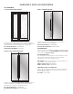
VARIANTS AND ACCESSORIES 42" MODELS CUSTOM-MADE PANEL DESIGN - Features custom-made panels and custom hardware provided by the cabinetmaker for a seamless appearance designed to blend with existing kitchen cabinetry. Base Model Numbers: JS42NXFXDE ARMOIRE KIT NUMBER: W10663564 NOIR™ STYLE STAINLESS DESIGN - RISE™ STAINLESS DESIGN - Features stainless steel wrapped doors and RISE™ handles with diamond-etched grip.
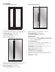
48" MODELS CUSTOM-MADE PANEL DESIGN - RISE™ STAINLESS DESIGN - Features custom-made panels and custom hardware provided by the cabinetmaker for a seamless appearance designed to blend with existing kitchen cabinetry. Features stainless steel wrapped doors and RISE™ handles with diamond-etched grip.
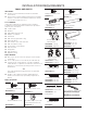
INSTALLATION REQUIREMENTS TOOLS AND PARTS IMPORTANT : Installer: Leave Installation Instructions with the homeowner. Homeowner: Keep Installation Instructions for future reference. Save these Installation Instructions for the local electrical inspector’s use. TOOLS NEEDED: Gather the required tools and parts before starting installation. Read and follow the instructions provided with any tools listed here.
LOCATION REQUIREMENTS WARNING OPENING DIMENSIONS IMPORTANT : The width of the opening (Width A), from side to side, must be as specified for your model for at least 2" (5.08 cm) back from the face of the cabinet. NOTE : If your opening does not meet this requirement, you will need to make modifications. Explosion Hazard Keep flammable materials and vapors, such as gasoline, away from refrigerator. Failure to do so can result in death, explosion, or fire.
The water shutoff should be located in the base cabinet on either side of the refrigerator or some other easily accessible area. If the water shutoff valve is not in the cabinets, the plumbing for the water line can come through the floor. See “Water Supply Requirements” for more information. ELECTRICAL REQUIREMENTS WARNING Electrical Shock Hazard B Dimension Plug into a grounded 3 prong outlet. Do not remove ground prong. Do not use an adapter. Do not use an extension cord. 84" (213.
WATER SUPPLY REQUIREMENTS REVERSE OSMOSIS WATER SUPPLY IMPORTANT : IMPORTANT : The pressure of the water supply coming out of a reverse osmosis system going to the water inlet valve of the refrigerator needs to be between 30 psi and 120 psi (207 kPa and 827 kPa). All installations must meet local plumbing code requirements. Connect to potable water supply only. Do not use with water that is microbiologically unsafe or of unknown quality without adequate disinfection before or after the system.
FRONT VIEW Width dimensions were measured from hinge to hinge. When leveling legs are fully extended to 1¹⁄₄" (3.2 cm) below rollers, add 1¹⁄₄" (3.2 cm) to the height dimensions. DOOR SWING DIMENSIONS The location must permit both doors to open to a minimum of 90°. Allow 4¹⁄₂" (11.4 cm) minimum space between the side of the refrigerator and a corner wall. NOTE : More clearance may be required if you are using wood overlay panels, custom handles, or extended handles.
PERMISSIBLE INSTALLATION OPTIONS OPTION 3—CLOSED SOFFIT OPTION 1—OPEN TO CEILING 6" (15.24 cm) min. 1/8" (3.2 mm) gap 84" (213.4 cm) 84" (213.4 cm) 1/8" (3.2 mm) gap OPTION 2—FALSE FRONT (CABINET FACE ONLY) 6" (15.24 cm) min. 1/8" (3.2 mm) gap STAINLESS STEEL PANEL KIT INSTALLATION REQUIREMENTS Refer instructions received with full height door panel kit. CUSTOM WOOD PANEL DIMENSIONS AND INSTALLATION REQUIREMENTS Refer instructions received with Armoire kit. 84" (213.
INSTALLATION INSTRUCTIONS UNPACK THE REFRIGERATOR 1. Place an appliance dolly under the left side of the refrigerator as shown. Place the corner posts from the packing materials over the trims as appropriate. Slowly tighten the strap. 2. Place pieces of the shipping carton on the floor when rolling the dolly and refrigerator into the house. Move the refrigerator close to the built-in opening. WARNING Tip Over Hazard Refrigerator is top heavy and tips easily when not completely installed.
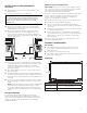
CONNECT TO WATER LINE TO INSTALL ANTI-TIP BOARDS 1. 2. Mark the stud locations on rear wall. PARTS NEEDED Securely attach two 2" x 4" x 32" (5 cm x 10 cm x 81 cm) boards to wall studs behind refrigerator. Use six #8 x 3" (7.6 cm) (or longer) wood screws. The wood screws must be screwed into the studs at least 1½" (3.8 cm). The boards must overlap the compressor cover. Minimum 7 ft (2.
1. 2. Unplug refrigerator or disconnect power. 3. Locate a 1/2" to 1¹⁄₄" (1.3 cm to 3.18 cm) vertical cold water pipe near the refrigerator. Turn OFF main water supply. Turn ON nearest faucet long enough to clear line of water. CONNECT TO REFRIGERATOR PARTS SUPPLIED 1/4" to 1/4" (6.35 mm to 6.35 mm) male-to-male coupling. IMPORTANT : Horizontal pipe will work, but drill on the top side of the pipe, not the bottom.
OVERMOLD COUPLING (ON SOME MODELS) PLUG IN REFRIGERATOR WARNING A B C Electrical Shock Hazard Plug into a grounded 3 prong outlet. Do not remove ground prong. Do not use an adapter. A. Household water line B. Nut (purchased) C. Ferrule (purchased) Do not use an extension cord. Failure to follow these instructions can result in death, fire, or electrical shock.
3. Using the original holes and the screws removed in Step 2, fasten the side trim to the refrigerator cabinet. NOTE : Make sure to fasten each trim piece to the side of the refrigerator cabinet from which it was removed. The tapered shaped edge should be forward with the notches aligning with the door hinges. After the refrigerator is leveled and aligned, remove the installation block from the door hinge and use it to check the spacing between the panels and adjacent cabinets.
LEVEL AND ALIGN REFRIGERATOR IMPORTANT : Adjust in small increments to keep from damaging the cabinet trim and causing problems with the door alignment or top grille fit. To avoid damage to the cabinet or leveling legs, do not apply more than 50 inch-pounds (5.65 Nm) of torque to the leveling bolts. The leveling legs can be extended to a maximum of 1¹⁄₄" (3.18 cm) below the rollers. WARNING 4. Tip Over Hazard INSTALL PANELS Refrigerator is top heavy and tips easily when not completely installed.
4. Trim the skirt by scoring the proper “V” groove with a utility knife. Break the skirt at the score line. COMPLETE INSTALLATION 1. Turn the water supply line valve to the “Open” 2. A 3. A. “V” groove 5. Using the 2 screws, attach the base grille assembly to the refrigerator as shown. NOTE : Drive in the right side screw first. 4. 5. 6. Turn the refrigerator switch to the ON position. See “Power On/ Off Switch” in the Use & Care Guide for instructions. Wait a few minutes.
INTRODUCTION SÉCURITÉ DU RÉFRIGÉRATEUR Votre sécurité et celle des autres est très importante. Nous donnons de nombreux messages de sécurité importants dans ce manuel et sur votre appareil ménager. Assurez-vous de toujours lire tous les messages de sécurité et de vous y conformer. Voici le symbole d’alerte de sécurité. Ce symbole d’alerte de sécurité vous signale les dangers potentiels de décès et de blessures graves à vous et à d’autres.
VARIANTES ET ACCESSOIRES MODÈLES DE 42 PO CONCEPTION DE PANNEAUX PERSONNALISÉS – STYLE ACIER INOXYDABLE RISE™ – Comporte des panneaux et du matériel personnalisés fournis par l’ébéniste pour une apparence harmonieuse conçue pour s’intégrer aux armoires de cuisine existantes. Portes avec habillage en acier inoxydable et poignées RISE™ avec surface de saisie à texture gravée (losanges).
MODÈLES DE 48 PO CONCEPTION DE PANNEAUX PERSONNALISÉS – Comporte des panneaux et du matériel personnalisés fournis par l’ébéniste pour une apparence harmonieuse conçue pour s’intégrer aux armoires de cuisine existantes. Numéros de modèles de base : JS48NXFXDE NUMÉRO D’ENSEMBLE POUR ARMOIRE : W10663564 ACIER INOXYDABLE NOIR™ – STYLE ACIER INOXYDABLE RISE™ – Portes avec habillage en acier inoxydable et poignées RISE™ avec surface de saisie à texture gravée (losanges).
EXIGENCES D’INSTALLATION OUTILS ET PIÈCES IMPORTANT : Installateur : Remettre les instructions d’installation au propriétaire. Propriétaire : Conserver les instructions d’installation pour référence ultérieure. Conserver ces instructions d’installation pour consultation par l’inspecteur local des installations électriques. OUTILS REQUIS : Rassembler les outils et pièces nécessaires avant d’entreprendre l’installation.
AVERTISSEMENT DIMENSIONS DE L’OUVERTURE IMPORTANT : La largeur de l’ouverture d’encastrement (largeur A) d’un côté à l’autre doit être telle que spécifiée par le modèle concerné, pour au moins 2 po (5,08 cm) en retrait de l’avant de l’armoire. REMARQUE : Si l’ouverture d’encastrement ne respecte pas cette condition, des modifications devront être apportées. Risque d'explosion Garder les matériaux et les vapeurs inflammables, telle que l'essence, loin du réfrigérateur.
Le robinet d’arrêt d’eau doit être situé dans l’armoire inférieure d’un côté ou l’autre du réfrigérateur, ou à un autre endroit facilement accessible. Si le robinet d’arrêt ne se trouve pas dans les armoires, la plomberie d’arrivée d’eau peut provenir du plancher. Voir les « Spécifications de l’alimentation en eau » pour plus de renseignements. SPÉCIFICATIONS ÉLECTRIQUES AVERTISSEMENT Risque de choc électrique B Dimension Brancher sur une prise à 3 alvéoles reliée à la terre.
SPÉCIFICATIONS DE L’ALIMENTATION EN EAU IMPORTANT : Toutes les installations doivent être conformes aux exigences des codes locaux de plomberie. Brancher sur une alimentation en eau potable uniquement. Ne pas utiliser pour le filtrage d'une eau microbiologiquement polluée ou de qualité inconnue en l'absence d'un dispositif de désinfection adéquat avant ou après le système.
VUE DE FACE Les dimensions de largeur ont été relevées d’une charnière à l’autre. Lorsque les pieds de nivellement sont totalement déployés de 1 ¹⁄₄ po (3,2 cm) au-dessous des roulettes, ajouter 1 ¹⁄₄ po (3,2 cm) à la hauteur totale. DIMENSIONS POUR L’OUVERTURE DES PORTES L’emplacement d’installation doit permettre l’ouverture des deux portes à un angle minimal de 90°. Laisser un espace libre d’au moins 4 ¹⁄₂ po (11,4 cm) entre le côté du réfrigérateur et un mur d’angle.
OPTIONS D’INSTALLATIONS PERMISES OPTION 1 – OUVERTURE VERS LE PLAFOND OPTION 3 – SOFFITE FERMÉ 6 po (15,24 cm) min. Espacement de 1/8 po (3,2 mm) 84 po (213,4 cm) 84 po (213,4 cm) 1/8 po (3,2 mm) gap OPTION 2 – AVANT DÉCORATIF (FAÇADE DE L’ARMOIRE UNIQUEMENT) 6 po (15,24 cm) min. 1/8 po (3,2 mm) gap EXIGENCES D’INSTALLATION DE L’ENSEMBLE DE PANNEAUX EN ACIER INOXYDABLE Consulter les instructions reçues avec l’ensemble de panneaux de porte pleine grandeur.
INSTRUCTIONS D’INSTALLATION DÉBALLAGE DU RÉFRIGÉRATEUR 1. Introduire un chariot de manipulation sous le côté gauche du réfrigérateur, comme illustré. Placer les coins de protection de l’emballage sur les garnitures comme il convient. Serrer lentement la sangle. 2. Placer des bouts du carton d’expédition sur le plancher lorsqu’on fait rouler le chariot et le réfrigérateur pour les faire entrer dans le domicile. Approcher le réfrigérateur près de l’ouverture d’encastrement.
INSTALLATION DES PLANCHES ANTIBASCULEMENT 1. 2. Marquer les emplacements des montants sur le mur arrière. Fixer solidement deux planches de 2 x 4 x 32 po (5 cm x 10 cm x 81 cm) sur les montants muraux derrière le réfrigérateur. Utiliser 6 vis à bois n° 8 x 3 po (7,6 cm) ou plus longues. Les vis à bois doivent pénétrer dans les montants d’au moins 1 ½ po (3,8 cm). Les planches doivent être placées en chevauchement sur le couvercle du compresseur.
1. 2. 3. Débrancher le réfrigérateur ou déconnecter la source de courant électrique. COUPER l’alimentation principale en eau. Ouvrir le robinet le plus proche assez longtemps pour vider l’eau du tuyau. Identifier une canalisation d’eau froide verticale de 1/2 po à 1 ¹⁄₄ po (1,3 cm à 3,18 cm) à proximité du réfrigérateur. 9. 10. Placer l’extrémité du tube dans un seau et OUVRIR 11. IMPORTANT : Vérifier qu’il s’agit d’une canalisation d’eau froide.
RACCORD PAR DESSUS LE SURMOULAGE (SUR CERTAINS MODÈLES) A B BRANCHER LE RÉFRIGÉRATEUR AVERTISSEMENT C Risque de choc électrique Brancher sur une prise à 3 alvéoles reliée à la terre. Ne pas enlever la broche de liaison à la terre. Ne pas utiliser un adaptateur. Ne pas utiliser un câble de rallonge. A. Canalisation d’eau du domicile B. Écrou (à acheter) C. Virole (à acheter) RACCORD DISCRET (SUR CERTAINS MODÈLES) A B C 6.
3. En utilisant les trous d’origine et les vis retirées à l’étape 2, fixer la garniture latérale à la caisse du réfrigérateur. REMARQUE : Veiller à fixer chaque garniture sur le côté de la caisse du réfrigérateur d’où elle a été retirée. Le bord de forme conique doit être en avant, les encoches alignées avec les charnières de la porte.
RÉGLAGE DE L’APLOMB ET ALIGNEMENT DU RÉFRIGÉRATEUR A B AVERTISSEMENT 2 po (5 cm) 84 po (213,4 cm) C Risque de basculement D Le réfrigérateur est lourd au sommet et bascule facilement lorsqu'il n'est pas complètement installé. Garder les portes fermées avec un ruban adhésif jusqu'à l'installation complète du réfrigérateur. A. Deux planches de 2 po x 4 po x 32 po (5 cm x 10 cm x 81 cm) B. Fixer aux montants avec six vis n° 8 x 3 po (7,6 cm). C. Couvercle du compresseur D.
INSTALLATION DE LA GRILLE DE LA BASE La grille de base comporte deux pièces permettant un ajustement personnalisé : la grille de base elle-même et la plinthe. La plinthe peut être ajoutée à la grille de la base pour la prolonger jusqu’au plancher. 1. Pour voir si la plinthe est nécessaire, placer la grille de la base en position. Ne pas fixer la grille de la base au réfrigérateur. Mesurer la distance entre le fond de la grille de la base et le plancher.
W10779523B /™ ©2019 JennAir. All rights reserved. Used under license in Canada. Tous droits réservés. Utilisé sous licence au Canada.