
Owner's Manual


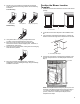


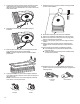


Table Of Contents
- RANGE SAFETY
- Range Safety
- RANGE MAINTENANCE AND CARE
- Clean Cycle
- General Cleaning
- INSTALLATION INSTRUCTIONS
- REQUIREMENTS
- Tools and Parts
- Location Requirements
- Venting Requirements
- Electrical Requirements - U.S.A. Only
- Electrical Requirements - Canada Only
- INSTALLATION
- Unpack Range
- Install Anti-Tip Bracket
- Position the Blower Location Template
- Install the Downdraft System
- Adjust Leveling Legs
- Level Range
- Electrical Connection - U.S.A. Only
- Install Blower
- Verify Anti-Tip Bracket Is Installed and Engaged
- Remove/Replace Drawer (on some models)
- Oven Door
- Complete Installation
- Moving the Range
- SECURITE DE LA CUISINIERE
- Sécurité de la cuisinière
- ENTRETIEN ET REPARATION DE LA CUISINIERE
- Programme de nettoyage
- Nettoyage général
- INSTRUCTIONS D'INSTALLATION
- SPECIFICATIONS
- Outils et pièces
- Exigences d’emplacement
- Exigences concernant l’évacuation
- Spécifications électriques – É.-U. seulement
- Spécifications électriques – Canada seulement
- INSTALLATION
- Déballage de la cuisinière
- Installation de la bride antibasculement
- Positionnement du gabarit indiquant l’emplacement du ventilateur
- Installation du circuit d’évacuation par le bas
- Réglage des pieds de nivellement
- Réglage de l’aplomb de la cuisinière
- Raccordement électrique – É.-U. seulement
- Installation du ventilateur
- Vérifier que la bride antibasculement est bien installée et engagée
- Enlever/replacer le tiroir (sur certains modèles)
- Porte du four
- Achever l’installation
- Déplacement de la cuisinière

18
3. Feed blower motor wire through opening and place the strain
relief bracket to the inside of the blower cover. Install and
tighten the two (2) provided #8–18 x 3/8" screws to secure the
strain relief bracket.
4. Reposition the blower motor cover retainer spring as
illustrated.
5. Remove paper from the rear of the rectangular felt pad and
apply adhesive side of felt to the bellow flange.
NOTE: This step is important to ensure maximum blower
performance.
6. Apply blower motor cover to the blower. Slightly spread the
cover retainer spring to allow the cover to drop into position on
the blower motor.
NOTE: The blower motor cover will not properly install if the
motor wire is on the top of the motor.
Incorrect correct
7. Rotate blower motor cover so the bellows are facing towards
the front of the installation.
8. Move blower motor wire to the front of the installation.
9. Remove the cardboard or hardboard from under the range.
10. Remove the front lower access panel of the range by gently
lifting on the panel then pull outward.
11. Using 2 or more people, gently move the range into its final
location.
12. Check to ensure the electrical cord are not kinked. Use a
flashlight to look underneath the bottom of and behind the
range.
13. Verify that the anti-tip bracket is installed and engaged.
� Use a flashlight to look underneath the bottom of and
behind the range.
� Visually check that the rear range foot is inserted into the
slot of the anti-tip bracket.
14. Rotate blower motor cover so the bellows are in their final
position. Ensure the rear of the bellow flange is engaged in the
retaining bracket.
A
A. Retaining
bracket
Final Position