
Installation Instructions


6
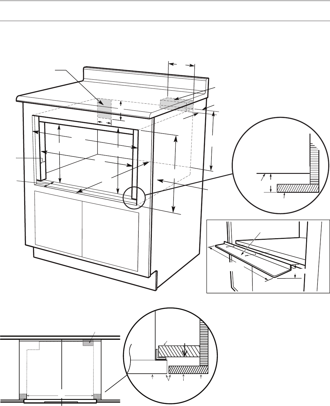
24” (61.00 CM) FLUSH MOUNT
Cabinet Preparation
Cabinet Dimensions
Top view
K
K
P
Q
Anti-Tip block
Mounting
cleat
Drawer
face
Cabinet
face
C
N
H
E
F
D
A
B
J
L
I
M
K
G
Note: the face of the shelf must
sit 1
3
/4" (44.45 mm) back from
the face of the cabinet.
Cabiet face
Shelf face
L
R
O
A. 6” (152.40 mm) minimum
16” (406.40 mm) maximum
B. Suggested electrical recepticle location
C. Anti-Tip block
D. 3” (76.20 mm)
E. 3
1
/
2
” (88.90 mm)
F. 4.5” (114.30 mm)
G. 24
3
/
16
” (614.35 mm) minimum
H. 14
13
/
16
” (376.24 mm) to bottom
of Anti-Tip block
I. 1” (25.40 mm) minimum
J. 24” (609.60 mm) minimum depth
K. 22
1
/
8
” (561.97 mm) “mounting cleat to
mounting cleat”
L. 1
7
/
8
” (47.62 mm)
M. 16
7
/
8
”(428.62 mm) opening
N. Platform must support 100 lb (45.4 kg)
O. 16
1
/
8
” (409.56 mm)
P. 0” (0 mm) = ush
Q. 1
17
/
32
” (39 mm)
R. 15
9
/
16
” (395.3 mm)
23 ¹¹/₁₆"
(601.66 mm)
³/₄" (19.05 mm)
Flush mount deector vent