AWM950 High Power AM/FM/DVD Player Owner’s Manual Designed Specifically for the Van and RV lndustries
Thank you for your purchase of the AWM950. It is designed to give you good value and many hours of listening enjoyment. Please read this manual carefully, as it should be able to answer many of your questions about the operation and features of this product.
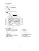
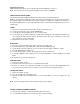
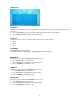
Controls Identification: Controls Identification 1) Tuning Up / Seek / Minute Set Button 2) Tuning Down / Seek / Hour Set Button 3) Mute / AS/PS / Loud Buttons 4) Time Set Button 5) Display Window 6) Alarm Set / Alarm On/Off Buttons 7) Button Reset 8) Preset # 3 (Previous) / Preset # 4 (Next) 9) Preset # 5 (Menu) 10) Preset # 6 (Enter) 11) Preset # 1 (Play/Pause) / Preset # 2 (Stop) 12) 13) 14) 15) 16) 17) 18) 19) 20) 21) 22) 23) 2 DVD Player Eject Button Speaker Selector 1/8” Auxiliary Input Jack Stere
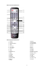
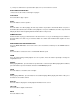
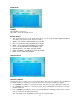
Remote Controls Identification Remote Controls Identification 1) Power 2) Source 3) Numeric Buttons 4) Mute 5) Tune Up 6) Tune Down 7) Previous 8) Left 9) Enter 10) Fast Reverse 11) Stop 12) Subtitle 13) Setup 14) Program 15) Audio (DVD) 16) Go To 17) Angle 18) 19) 20) 21) 22) 23) 24) 25) 26) 27) 28) 29) 30) 31) 32) 33) 3 Eject Menu/Band Audio Mode Vol + Vol – Up Next Right Down Fast Forwarding Play / Pause Display Title Repeat Time / Freq Zoom
Operating Instructions: NOTE: Number in parenthesis (#) corresponds with “Control Identification” on page 3. Note : Power can be turned on by pushing any button on the front of the AWM950. LIQUID CRYSTAL DISPLAY PANEL The liquid crystal display (LCD) panel displays the frequency, time and activated functions. Note: It is characteristic of LCD panels that, if subjected to cold temperatures for an extended period of time, they will take longer to illuminate than under normal conditions.
3) Then press and hold one of preset buttons (8,9,10 or 11) for more than 3 seconds. DVD PLAYBACK OPERATIONS ***Please refer to the remote control figure on page 4. PLAY/PAUSE Press the button to play or pause. EJECT Press this button to load or eject disc. STOP Press this button once when playing, the unit stops and the stop location is memorized.
SETUP Press this button to enter setup menu. PREVIOUS/NEXT Press this button to go to the PREVIOUS/NEXT chapter, track or song. TITLE For DVD discs, press this button to enter the title menu, press the DIRECTION buttons and PLAY button to select and play (only if supported by the discs). MENU Press this button once to return to the root menu.
SCREEN SAVER This item is used to open/close SCREEN SAVER On: Screen saver will automatically be executed if the screen keeps still for whole fifteen minutes OFF : Screen saver would not be executed in any situation LOAD SETUP DEFAULT This item is used to restore all menus as factory defaults, except the item related to Parent Control Sub-item.
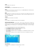
VIDEO SETUP TV SCREEN Which picture format appears on your TV depends on what kind of TV you have and the picture mode your TV is set to; 4:3 – LETTER BOX refers to pictures where black bands appear at the top and bottom. 16:9 – WIDE SCREEN for wide screen TV (Full mode) TV OUTPUT This item is used to select a TV signal system to match your TV set.
AUDIO SETUP CHANNEL 2CH STEREO – Select stereo 2CH LT/RT – Select left and right channel DIGITAL OUTPUT SET – Each DVD disc has its own Audio output options. You can set up the DVD’s Digital Audio Output according to your speaker system.
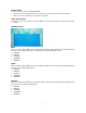
CHANGING PARENTAL CONTROL PASSWORD Use UP/DOWN arrow buttons to select Password item. Enter old 4 – digital security code Then enter new 4 digital security code Press UP/DOWN arrow button to exit Note : New 4 – digital security code will take effect after closing the Setup menu. NOTE : It is necessary to stop the disc playback if you want to enter the PREFERENCES MENU ITEM. In PREFERENCES MENU ITEM, the system default password is 0000.
Hook up wiring color code.
Installation: 1) Cut a mounting hole in the desired location using mounting hole diagram (below) and use the four 3x20min self tapping screws provided to mount the unit. 2) Route power, speaker and antenna cables through hole and connect to unit as outlined in the Wiring Color Code diagram on the previous page. 3) After making sure connections are correct, test operation.
WARRANTY 90 DAY / 12 MONTH LIMITED WARRANTY AUDIOVOX SPECIALIZED APPLICATIONS, LLC (the Company) warrants to the original retail purchaser of this product that should this product or any part thereof, under normal use and conditions, be proven defective in material or workmanship within 90 days from the date of original purchase, such defect(s) will be repaired or replaced (at the Company’s option) without charge for parts and repair labor.