
Installation Sheet

INSTALLATION INSTRUCTIONS
RZ-T1X
Cove / Cabinet / Showcase / Display
LED Surface Mount Series
www.jescolighting.com
support@jescolighting.com
Tech Support: 855.592.0029
Instruction sheet subject to change without prior notice.
15 Harbor Park Drive
Port Washington, NY 11050
Main Line: 800.527.7796
Fax Line: 855.265.5768
219 South 6th Ave
City of Industry, CA 91746
Main Line: 855.654.0110
Fax Line: 626.333.2955
REV1
JW030315
Page 1
Please read and save these instructions. Read carefully before using product. Failure to comply
with instructions could result in personal injury and/or damage to product or property. Please
retain instruction sheet for future reference.
TOOLS REQUIRED HARDWARE INCLUDED
2X MOUNTING SCREWS 14X WIRE CLIP
PHILLIPS SCREWDRIVER HAMMER
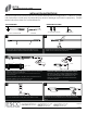
3
1
4 5
2
REMOVE LED MODULES FROM TRACK, SECURE TRACK ON
MOUNTING SURFACE WITH INCLUDED MOUNTING SCREWS.
PLUG IN POWER SUPPLY (24W) INTO A POLARIZED OUTLET.
MOUNT LED MODULES ON TO TRACK. MAKE SURE EACH
MAKES GOOD CONTACT WITH THE TRACK.
AFTER ALL THE LED MODULES ARE MOUNTED, PLUG IN POWER FEED
CABLE INTO TRACK’S POWER INPUT.
Note: If cable plugged into the other end the track the dimmer/on-off
switch will not work
USE PROVIDE WIRE CLIPS TO SECURE CORD ON SURFACE WITH A
HAMMER. CAREFUL NOT TO DAMAGE THE CORD.
(Recommended to place a wire clip every 5 inches)
PRESS BUTTON ON POWER ENDCAP TO TURN ON THE FIXTURE.
PRESS AND HOLD THE POWER BUTTON TO DIM EACH LED PUCK
HEAD.
C
L
I
C
K
Ø3/8”
1-3/4”
INSTALLING POWER SUPPLY BEHIND MOUNTING SURFACE
MEASURE 1-3/4” AWAY FROM POWER ENDCAP, DRILL A
3/8” HOLE. THREAD THE POWER CONNECTOR THROUGH
THE HOLE AND CONNECT TO POWER ENDCAP. USE
WIRE CLIP IF NECESSARY TO ORGANIZE CORD BEHIND
MOUNTING SURFACE.
5”
WIRE CLIP
MOUNTING SURF
ACE
CORD