
How to Guide

MONORAIL SYSTEM
5 Steps To Creating A Basic Configuration:
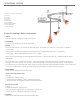
Components of the Monorail System:
A Monorail
B End cap
C Connector
D Standoff
E Transformer
F Fixture Adapter
G Quick Adapt Pendant
H Quick Adapt Spot
I Fixture Extension
A
E
D
F
C
F
D
I
G
H
H
B
D
F
1. LAYOUT
Start with creating a design of the Monorail System.
2. SUSPENSION
Determine how the Monorail is to be suspended.
3. POWER
Monorail is rated at 25A. This means the Monorail system will handle up to 300W on a 12V system; or 600W on
a 24V system.
Start by adding up the total wattage of all the Pendants and Spots being used on the configuration.
For example, 6 Quick Adapt Pendants x 50W each = 300W.
Match up the total wattage with the appropriate transformer. In the example above, a 300W transformer will be
appropriate.
The transformer is key to the Monorail system. If the total wattage of Pendants and Spots exceed the transformer
wattage, you have 2 options. You can use a lower wattage lamps for the Pendants and or Spots. Another option
is to introduce a second transformer. When using a second transformer, the power will be isolated. A non-conductive
connector may be used to create a continuous run but powered by two separate power sources.
4. TRANSFORMER
Determine the appropriate transformer type.
Surface Mounted Transformers
Features:
• Installed in a finished ceiling.
• The transformer is visible, it is part of the Monorail System.
• Select Electronic or Magnetic Surface Mounted Transformer.
Remote Transformers
Features:
• Installed behind the ceiling or wall.
• The transformer is hidden from view, provides a cleaner look.
• Select Electronic or Magnetic Remote Transformer.
5. ELEMENTS
Select Quick Adapt Pendants and/or Quick Adapt Spots.