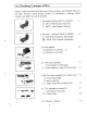
A. Checking Contents of Box Check to make sure that all of the items shown as below are included with your 2.4 GHz Wireless Video Sender System. If something is missing, please contact your dealer as soon as possible. 1. Transmitter [Modeling or 2065TH] x1 [J 2061ST W/O Remote Receiver [J 2065TH with Remote Receiver 2. Receiver [Model 2061R or 2065R] X1 [1 2061R W/O Remote Transmitter IW 2065R with Remote Transmitter 3. Power adapter X2 [1(230VAC to 12VDC) or CI(120VAC to 12VDC) 4. TIT hook-up cable, x1 9.
Important-Safety Precautions To prevent fire or shock hazard, do not expose this product to rain or moisture. Do not use near a bathtub, wash bowl, Kitchen sink, or laundry tub, in a wet basement, or near a swimming pool. To avoid electrical shock, do not open this product. This product should be operated to use only the power supply included with it or provided as an accessory. Do not overload wall outlets and extension cords as this can result in the risk of fire or electrical shock.
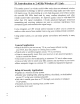
B. Introduction to 2.4GHz Wireless AV Link This sender system is a wireless audio/video sender that uses advanced wireless communication technology to deliver consistently sharp audio and video up to 100 meters away. By transmitting at a very high frequency (2.4 avoids the crowded 900 MHz band used by many cordless telephones and other ‘wireless audio/video transmitters. It’s superior quality is due to wide-band FM rather than AM signal modulation.
Attention I. The outlet of the power supply must have the same voltage as the local area. 2. Be sure the transmitter and the receiver connect the equipment correctly (e.g. the transmitter connect the VCR, the receiver connect the TV). The 21 PIN scary cable cannot exchange the connector of both transmitter and the receiver. 3. Keep the antenna plate open to aid ventilation. 4. When switch is off from transmitter or receiver, it needs to wait for a few seconds in order to restart again, 5.
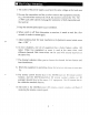
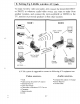
C. 2061T/2061R Panel Controls and Features The following illustrations show the names of each component, button and switch connectors on the transmitter and receiver. FRONT VIEW FOR TRANSMITTER AND RECEIVER Directional 2.
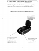
REAR VIEW FOR TRANSMITTER (20617) Power on/off switch DC power output port (12VDC, 100mA max.) {Make sure the ON/OFF switch is locate the OFF Position before use) Audio Left (white) in -Audio Right (red) in Video Jack (yellow) in DC power input. connect to power adaptability) REAR VIEW FOR RECEIVER (2061R) ( QTE 13. fos 1) Fez: nOGIM2005R Power on/off switch Channel select CH3 or CH4 (SCENT only) RF output power output port {12VDC, 50mA max.
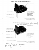
D. 2065T/2065R Panel Controls and Features The following illustrations show the names of each component, button and switch connectors on the transmitter and receiver. FRONT VIEW FOR TRANSMITTER AND RECEIVER UHF antenna sends and Directional 2.
REAR VIEW FOR TRANSMITTER (2065TH) IR extender output port Power on/off switch DC power output port {12VDC, 100mA max.) for approved accessory Audio Left (white) in Audio Right (red) in DC power input. connect to power adaptability) Video Jack (yellow) in REAR VIEW FOR RECEIVER (2065R) Trt tov Power convoy switch DC power output port {12VDC, So Ma max.
E. Setting Up 2.4GHz wireless AV Link To enjoy wireless video and audio, just connect the neurotransmitter or 2065TH) to whatever audio/video source you want to enjoy from another location, and connect the receivership or 2065R) to the TV, monitor or powered speakers in that other location. ROOM 1 SAT Receiver ) \, 2061R or 2065R 7 ot I Receiver \, i” MN) {Camera} Camcorder 2061ST or 2065TH Transmitter Multi-Media Remote PC Controller Stereo and more...
coin sure the ON/OFF switch is in th /;position before connection. B® How To Transmit Audio/Video from Your VCR 1 . Connect one set of audio/video (A/V) cables (or scary cable labeled "Sender”) to the A/V jacks of the transmitter(20617 or 2065TH) and to the A/V output jacks (or scary connector) on the back of your VCR. Be sure the yellow. red and white plugs match the yellow, red and white jacks on both the VCR and the transmitter. If the VCR has only ong output for audio (mono sound only) .
BM How To Transmit Audio/Video from Your Satellite Receiver You can transmit audio/video either directly from your satellite receiver, or by connecting them to your VCR. To transmit directly from your satellite receiver, follow the instructions below. 1.Connect one set of audio/video (A/V) cables (or scary cable labeled "Sender™) to the A/V jacks of the neurotransmitter or 2065TH) and to the AUDIO/VIDEO OUT jacks (or scary connector) of the satellite receiver or laser disc player.
BM How To Receive Wireless Audio/Video Signals on Your TV There are two ways to receiver wireless audio/video signals on your remote TV (TV in another location such as in bedroom, kitchen). + Connect the receiver directly to the remote TV.
M Connecting Receiver to Remote TV through VCR This setup enables you to record transmitted audio and video on your remote VCR and also enjoy the picture and sound on a remote TV at the same time. 1.Connect one set of audio/video (A/V) cables to the A/V output jacks of the receiver (2061R or 2065R) and to the A/V input jacks on your VCR. Be sure the yellow, red and white plugs match the yellow, red and white jacks on both the receiver and the VCR.
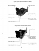
Gene F. Orienting Units for Optimum Performance This sender system should be placed on a flat, stable surface to prevent damage to it from falling. For Optimum performance, both the audio/video and remote control antennas should be carefully oriented as described below.
REMOTE CONTROL ANTENNA £2085T ONLY) ANTENNA REMOTE ANTENNA PITTED CONTROL PITTED SIDE ANTENNA ANTENNA SIDE PITTED SIDE ANTENNA PITTED : SIDE REMOTE TRANSMITTER CONTROL (Front View} ANTENNA (2065R ONLY) REMOTE RECEIVER CONTROL (Front View) ANTENNA (QUASAR ONLY) a TRANSMITTER RECEIVER (Front View) (Front View) Fig-2 Fig-3 Orienting the Remote Control Antennas In order to obtain optimum performance of the remote control extender, the remote control -extender, the remote control antennas should also be oriented
G. Using the Remote Control Feature (2065TH/ 2065K only) This sender system not only allows you to send crisp audio/video from one area to another, it also gives you the ability to control the source using your existing remote control device.
H. Troubleshooting , Care and maintenance Please read this owner's manual carefully and follow the steps described in it. If you still have difficulties, consult the following table. It will guide you though the most common problems and their solutions. Problem Possible solution » Check all cable connections. » Make sure power plugs are pushed all the way in. « Check power switches on the remote TV and video source. { VCR. laser disc player, satellite receiver, ect.
Y18 Mua Pepin Tx Door: NUWPSH2IP5R I. Specifications Transmitter: 2061T/2065T Operating Frequency Band GHz Output Level 90 dBuv/m at 3 meters Modulation FM (video and audio) Channel PLL frequency synthesizer, 4 channels Video Input Level omit Audio Input Level 1V p-p @ 6000hm .