
User's Manual


DC power input, connect
to power adapter (9VDC
)
DC power input, connect
to power adapter (9VDC)
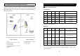
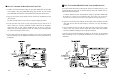
C. Product Layout
The following illustrations show the names of each component,
button and switch connectors on the transmitter and receiver.
FRONT VIEW FOR RECEIVER
LED
5
REAR VIEW FOR TRANSMITTER
Channel
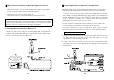
REAR VIEW FOR RECEIVER
CH4 (NTSC only)
RF output to TV
(e.g.
2058R
)
6
Power on/off switch
Channel
Switch
MINI DIN AV Jack
Power on/off switch
Channel
Switch
MINI DIN AV Jack
IR remote
control window