OWNER’S MANUAL DISHWASHER INSTALLATION AND MAINTENANCE Model 737E For operator. Do not discard.
Welcome to JET-TECH “Creating endless possibilities!” We have included information to help troubleshoot problems and facilitate resolving those problems. General information pertaining to our hi-temp ware washers will be covered in this manual. Specific information on our current and older models is available upon request, model by model. If you find any discrepancy or can’t find certain information, please contact us. We will be glad to be of assistance.
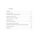
Contents WARRANTY....................................................................................................4 MACHINES SPECS........................................................................................5 GENERAL INSTALLATION GUIDELINES......................................................6 CONNECTING YOUR 737E........................................................................7,8 CHEMICAL PUMP ADJUSTMENT............................................................9, 10 CONTROL PANEL...
MANUFACTURERS LIMITED WARRANTY MVP GROUP CORPORATION (Jet-Tech Systems) hereby warrants all new warewashers bearing the name “JET-TECH” and installed within the continental United States of America or Canada to be free from defects in material and workmanship, under normal and regular usage and operation, for a period of one (1) year following the date of original installation (unless specified otherwise) but in no event can exceed eighteen (18) months from the date of shipment from the factory.
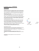
Connecting your new 737 **WATER SUPPLY** A 3/4” NPT fitting is required with 30 psi. dynamic pressure. A water pressure regulator* may be required. The water flow pressure cannot be less than 30 psi or exceed 30 psi. If the water pressure exceeds the prescribed amount, you will get inconsistent washing temperature, premature failure and thus may void the warranty. Incoming water temperature must be 140º F (60º C).
Installation 737 , continued ELECTRICAL ELECTRICAL A 208-240 volt, 60 Hz, Single Phase circuit is required for this unit. Check the rating plate on the front of the machine for the amp draw. In spite of the fact that the rating plate shows 208 volts, the unit is designed function properly on 208 volts to 240 volts. The top & back panels must be removed for the electrical hook -up. The top panel is secured by two Phillips head screws.
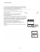
CHEMICAL PUMPS The model 737E is supplied with factory installed liquid detergent and rinse additive pumps to automatically dispense during each wash & rinse cycle. Before accessing the bottom section of the dishwasher, make sure that the power is turned off at the source (breaker panel). The bottom panel can only be removed with a flat tool like a screwdriver. Insert the screw-driver in the gap between the front panel and the side panel. Pry open towards you. Do this on both sides.
VISUAL CHEMICAL DELIVERY VERIFICATION The peristaltic chemical pumps are located in the base of the dishwasher. They feature a transparent cylinder (1) to visually see if fluid is passing through the pumps. The pumps are automatically energized during the “initial fill” (when turning on the dishwasher) and “rinse cycle” (after the wash cycle). During this time, the flow indicator (2) will move between the “Min Flow” position and the “Max Flow” position (3) in the cylinder.
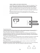
CONTROL PANEL LEGEND A = On/Off B = StartWashingCycle C = Short Washing Cycle D = Medium Washing Cycle E = Long Washing Cycle G = Drain Water Tank I = Wash Temperature Indicator L = Rinse Temperature Indicator Q = Display Panel I-L E D G C 11 Q B A
STARTING THE MACHINE 1- Verify that there are sufficient levels of detergent and rinse additive. The end weight at the end of the red (detergent) and blue (rinse) supply tubes must be at the bottom of the chemical containers. The chemicals will automatically dispensed at the appropriate times. 2- Open the dishwasher door and verify that all internal components, filters, wash arms and drain tube, are in their correct positions. (Fig.1) 3- Close the door and press button “A” to turn ON the machine. (Fig.
THERMO STOP This machine is equipped with THERMO STOP function. When activated, if necessary, it will extend the length of the wash cycle until the booster water is at the proper temperature. This device ensures correct final sanitization of the dishes. - When the Thermo Stop function is working, “SAFE” is displayed ion the control panel until final rinse temperature is reached and the cycle is finished. (Fig.7) STANDARD LOADING RACKS 1- Load the Clipper Pans in the special rack. (Fig.
DAILY CLEANING & MAINTENANCE/ END OF WORK 1- In order to have excellent washing results and maintain a clean wash tank, it is recommended to change the water of the machine at least twice a day and clean all the filters inside the tank. 2- Filters must only be removed once all the water is drained out of the machine. Any debris in the wash tank should be scooped out and not flushed down the dishwasher drain.
WARNING MESSAGES DISPLAYED ON THE CONTROL PANEL NOTE: If the machine is in OFF mode, warning messages are not displayed. Turn ON the machine to see the Error Message.. BOOSTER TEMPERATURE PROBE ERROR MESSAGES TEMPERATURE PROBE Booster temperature probe damaged or not connected. CALL TECHNICAL SERVICE ASSISTANCE TANK TEMPERATURE PROBE TANK TEMPERATURE PROBE Tank temperature probe damaged or not connected.
THE DISHWASHER DOES NOT WORK ? 1- Verify inlet main water supply is correctly connected, open and free from any obstructions. 2- Verify main electrical supply is working without any electrical breakdown connections. 3- Verify the door is properly closed. DISHWASHER DOES NOT WASH WELL ? 1- Verify if the filters are cleaned, in case not, clean them. 2- Verify if the washing water jets on the washing arms are not obstructed by any solid residues.