OWNER'S MANUAL HVBS-56M Horizontal/Vertical Bandsaw JET EQUIPMENT & TOOLS, INC. A WMH Company www.jettools.com P.O. BOX 1349 Auburn, WA 98071-1349 e-mail jet@jettools.
Important Information 1-YEAR JET offers a one-year limited warranty on this product LIMITED WARRANTY REPLACEMENT PARTS Replacement parts for this tool are available directly from JET Equipment & Tools. To place an order, call 1-800-274-6848. Please have the following information ready: 1. Visa, MasterCard, or Discover Card number 2. Expiration date 3. Part number listed within this manual 4. Shipping address other than a Post Office box.
WARNING Read and understand the entire instruction manual before operating machine. This machine is designed and intended for use by properly trained and experienced personnel only. If you are not familiar with the proper safe use of bandsaws, do not use this machine until proper training and knowledge has been obtained. • • • • • • • • • • • • • • • • • • • • • • • • • • • Always wear approved safety glasses/face shields while using this machine. Make certain the machine is properly grounded.
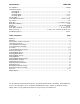
Specifications: HVBS-56M Stock Number................................................................................................................................ 414458 Horizontal Capacity: Round @ 90°....................................................................................................................................5” Round @ 45°....................................................................................................................................3” Rectangle @ 90° ........
Unpacking and Clean-Up Note: Read and understand the entire manual before attempting setup or operation. 1. Remove all contents form the shipping carton. 2. Inspect contents for shipping damage and report any damage to your distributor. 3. Wipe bed and vise assembly with clean cloth to remove excess oil used to prevent rust. 4. Do not discard any packing material until saw has been assembled and is running properly. Tools Supplied for Assembly 1.
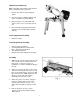
5. Attach a cross brace to the opposite end of the bed using three 5/16”x1” hex cap bolts, six 5/16” flat washers, and secure with three 5/16” hex nuts. Tighten the nut on the end of the bed first followed by the nuts on the sides. 6. Attach a leg to the cross brace using four 5/16”x3/4” carriage bolts, four 5/16” flat washers and four 5/16” hex nuts. Use a 12mm wrench to tighten. Repeat for other leg. 7. Attach the adjustable feet (A, Fig.
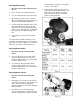
11. Slide pulley cover (A, Fig. 5) around motor shaft and worm gear shaft. Secure with two hex cap screws and washers (B, Fig. 5). 12. Lift motor with one hand while the other hand places V-belt (C, Fig.5) on both pulleys. 13. Attach the tension bracket (D, Fig. 5) to the saw bow with one 5/16”x3/4” hex head bolt and flat washer (E, Fig. 5). 14. Connect the two tension brackets with one 5/16”x3/4” carriage bolt, one 5/16” flat washers and one 5/16” hex nut (F, Fig. 5).
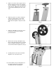
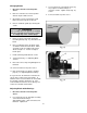
4. Remove two screws (D, Fig. 7) and plate (E, Fig. 7). 5. Guide blade through slot in table (A, Fig. 8) and fasten table with two screws (B, Fig. 8). 6. Fasten support bracket to underside of table using screw (C, Fig. 8) and hex nut. 7. Tighten bolt (B, Fig 7). Electrical Connections WARNING All electrical connections must be completed by a qualified electrician. Failure to comply may cause serious injury! The HVBS-463 bandsaw is rated at 115/230V and comes from the factory prewired 115V.
the blade guide assemblies as far apart as possible. Lock in place. Changing Blade Speed 1. Disconnect the machine from the power source. 4. Depress blade. Finger pressure should cause approximately .004" deflection. Turn blade tension knob (B, Fig. 12) until the proper tension is achieved. Re-position guides for cutting material. 2. Place saw arm in the horizontal position. 3. Loosen tensioning plate hex nut (A, Fig.10). 4. Open pulley cover (B, Fig. 10).
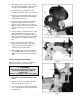
Changing Blades 1. Disconnect machine from the power source. 3. Loosen nut (B, Fig. 14) and turn nut (C, Fig. 14) to adjust eccentric bearing to a clearance of .001". Tighten nut (B, Fig. 14) to lock. 2. Raise the saw arm to the vertical position and lock in place with lock lever. 4. Connect machine to power source. 3. Open blade cover by removing the small knob found on the topside of the bow. 4. Remove red blade guards by removing two screws.
feed pressure. If they are still burned and heavy, reduce the blade speed. Optimum feed pressure has been set when the chips are curled, silvery, and warm. Adjusting Blade Tracking WARNING Blade tracking adjustment requires running the saw with the back cover open! This adjustment must be completed by qualified persons only! Failure to comply may cause serious injury! Blade tracking has been set at the factory and should not need adjustment. If blade tracking needs to be adjusted: 1.
2. Place saw arm in the horizontal position. Adjusting Automatic Shut-Off 3. Remove screws (A, Fig. 18) from the gear box and remove cover plate and gasket. The saw should stop after the cut has been completed: • If the saw completes the cut and continues to run, adjust the stop tip (A, Fig. 17) down. • If the saw shuts off before the cut is complete, adjust the stop tip (A, Fig. 17) up. • If the saw stops cutting but continues to run, adjust the stop bolt (B, fig. 17) down. 4.
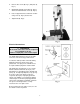
Breakdown for Bow Assembly 13
Breakdown for Base Assembly 14
Parts List for the HVBS-56M Bandsaw Index Part No. No. Description Size Qty. 1..........TS-0051031 ..............................Hex Cap Bolt......................................... 5/16”x3/4” ................... 4 2..........TS-0561011 ..............................Hex Nut................................................. 1/4”............................. 1 3..........TS-0680021 ..............................Flat Washer........................................... 1/4”............................. 5 4...
Index Part No. No. Description Size Qty. 52 ........TS-0081071 ..............................Hex Cap Bolt......................................... 5/16”x1-1/2” ................ 1 53 ........TS-0091071 ..............................Hex Cap Screw ..................................... 7/16”x2” ...................... 1 54 ........HVBS56M-054 ..........................Pivot Bracket......................................... ................................... 1 55 ........HVBS462-055 ..........................
Index Part No. No. Description Size Qty. 99 ........HVBS462-099 ...........................Spacer .................................................. ................................... 1 100 ......HVBS462-100 ...........................Flat Cross Head Screw.......................... 5/32”x3/8” ................... 8 101 ......HVBS462-101 ...........................Worm Gear Pulley................................. ................................... 1 102 ......TS-0720081 ..............................