PORTABLE FORCED AIR HEATERS OWNER’S MANUAL 100 SIDE PV 002 J100ECA 100,000 BTU/Hr 150 SIDE PV 004 J150ECA 150,000 BTU/Hr IMPORTANT Read and understand this manual before assembling, starting or servicing heater. Improper use of heater can cause serious injury. Keep this manual for future reference.
CONTENTS SECTION PAGE Safety Information ......................................................................... 3 Product Identification .................................................................... 4 Unpacking ...................................................................................... 5 Assembly ....................................................................................... 5 Theory of Operation ...................................................................... 6 Fuels .
SAFETY INFORMATION ! WARNINGS IMPORTANT: Read this Owner’s Manual carefully and completely before trying to assemble, operate, or service this heater. Improper use of this heater can cause serious injury or death from burns, fire, explosion, electrical shock, and carbon monoxide poisoning. ! DANGER Carbon monoxide poisoning may lead to death! Early signs of carbon monoxide poisoning resemble the flu, with headaches, dizziness, and/or nausea. If you have these signs, the heater may not be working properly.
PRODUCT IDENTIFICATION Hot Air Outlet Upper Shell Lower Shell Fuel Cap Fan Guard Fuel Tank Side Cover Power Cord Figure 1 - 100,000 BTU/Hr Model Hot Air Outlet Upper Shell Lower Shell Air Filter End Cover Fuel Cap Fan Guard Fuel Tank Power Cord Figure 2 - 150,000 BTU/Hr Model 4
UNPACKING ASSEMBLY 1. Remove all packing items applied to heater for shipment. 2. Remove all items from carton. 3. Check items for any shipping damage. If heater is damaged, promptly inform dealer where you bought heater. These models are furnished with wheels and handles. Wheels, handles, and the mounting hardware are found in the shipping carton. Tools Needed • Medium Phillips Screwdriver • 3/8" Open or Adjustable Wrench • Hammer 1. Slide axle through wheel support frame. Install wheels on axle.
THEORY OF OPERATION The Fuel System: The air pump forces air through the air line. The air is then pushed through the burner head nozzle. This air causes fuel to lift from the tank. A fine mist of fuel is sprayed into the combustion chamber. The Air System: The motor turns the fan. The fan pushes air into and around the combustion chamber. This air is heated and provides a stream of clean, hot air. The Ignition System: The electronic ignitor sends voltage to the spark plug.
VENTILATION ! WARNING Follow the minimum fresh, outside air ventilation requirements. If proper fresh, outside air ventilation is not provided, carbon monoxide poisoning can occur. Provide proper fresh, outside air ventilation before running heater. Provide a fresh air opening of at least three square feet (2800 square cm) for each 100,000 BTU/Hr rating. Provide extra fresh air if more heaters are being used.
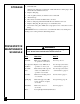
STORAGE PREVENTATIVE MAINTENANCE SCHEDULE 8 1. Drain fuel tank. Note: Locate drain plug on underside of fuel tank. Remove drain plug to drain all fuel. Be sure all fuel is removed. 2. Replace drain plug. 3. Add one gallon (4 liters) of clean kerosene to fuel tank. 4. Attach fuel cap. 5. Move heater forwards and backwards to stir fuel. 6. Remove drain plug and drain fuel tank. Be sure all fuel is removed. 7. Replace drain plug. Properly dispose of old and dirty fuel. 8. Store heater in dry place.
TROUBLESHOOTING ! WARNING Never service heater while it is plugged in, operating, or hot. Severe burns and electrical shock can occur. OBSERVED FAULT POSSIBLE CAUSE REMEDY Heater burns, but creates puffs of smoke. Heater will not burn steady. Heater burns with odor. Heater smokes continuously. A) Water in fuel B) Wrong fuel A) Check fuel tank for bubbles of water in bottom. If found, remove fuel and clean tank (see Storage, page 8). B) Remove wrong fuel and clean tank (see Storage, page 8).
SERVICE PROCEDURES Upper Shell Removal ! WARNING Never service heater while it is plugged in, operating, or hot. Severe burns and electrical shock can occur. Upper Shell 1. Remove screws along each side of heater using 5/16" nut-driver. These screws attach upper and lower shells together. 2. Lift upper shell off. 3. Remove fan guard.
Fuel Filter Fuel Filter, Bushing, and Lower Fuel Line (100,000 BTU/Hr Model) Upper Fuel Line 1. Remove side cover screws using 5/16" nut-driver. 2. Remove side cover. 3. Pull upper fuel line off fuel filter neck. 4. Carefully pry bushing, lower fuel line, and fuel filter out of fuel tank. 5. Wash fuel filter with clean fuel and replace in tank. 6. Attach upper fuel line to fuel filter neck. 7. Replace side cover.
Spark Plug 1. Remove upper shell (see page 10). 2. Remove fan (see page 17). 3. Remove spark plug wire from spark plug. 4. Remove spark plug from burner head using 13/16" open-end wrench. 5. Clean and regap spark plug electrodes as follows: .055" (1.4 mm) = 100,000 BTU/Hr model .075" (1.9 mm) = 150,000 BTU/Hr model 6. Install spark plug in burner head. 7. Attach spark plug wire to spark plug. 8. Replace fan (see page 17). 9. Replace fan guard and upper shell.
Air Output, Air Intake, and Lint Filters 1. Remove upper shell (see page 10). 2. Remove filter end cover screws using 5/16" nutdriver. 3. Remove filter end cover. 4. Replace air output and lint filters. 5. Wash or replace air intake filter (see Preventative Maintenance Schedule, page 8). 6. Replace filter end cover. 7. Replace fan guard and upper shell. IMPORTANT: Do not oil filters.
Nozzle (100,000 BTU/Hr Model) 1. Remove upper shell (see page 10). 2. Remove fan (see page 17). 3. Remove fuel and air line hoses from burner head. 4. Remove spark plug wire from spark plug. 5. Remove spark plug from burner head using 13/16" open-end wrench. 6. Remove three screws using 5/16" nut-driver and remove burner head from combustion chamber. 7. Place burner head into vise and lightly tighten. 8. Carefully remove nozzle from burner head using 5/8" socket wrench (see Figure 15). 9.
Nozzle (150,000 BTU/Hr Model) 1. Remove upper shell (see page 10). 2. Remove fan (see page 17). 3. Remove spark plug wire from spark plug. 4. Remove spark plug from burner head using 13/16" open-end wrench. 5. Loosen flare nut using 3/4" open-end wrench. Push fuel tube down. 6. Remove air line hose from burner head. 7. Remove three screws using 5/16" nut-driver and remove burner head from combustion chamber. 8. Place burner head into vise and lightly tighten. 9.
Pump Rotor Blade (Procedure if rotor is binding) 1. Remove upper shell (see page 10). 2. Remove filter end cover screws using 5/16" nutdriver. 3. Remove filter end cover and air filters. 4. Remove pump plate screws using 5/16" nutdriver. 5. Remove pump plate. 6. Remove rotor, insert, and blades. 7. Check for debris in pump. If debris is found, blow out with compressed air. 8. Install insert and rotor. 9. Check gap on rotor. Adjust to .003"/.004" (.076/.101mm) if needed (see Figure 19).
Fan IMPORTANT: Remove fan from motor shaft before removing motor from heater. The weight of the motor resting on the fan could damage the fan pitch. 1. Remove upper shell (see page 10). 2. Use 1/8" Allen wrench to loosen setscrew which holds fan to motor shaft. 3. Slip fan off motor shaft. 4. Clean fan using a soft cloth moistened with kerosene or solvent. 5. Dry fan thoroughly. 6. Replace fan on motor shaft. Place fan hub flush with end of motor shaft (see Figure 22). 7. Place setscrew on flat of shaft.
Blue WIRING DIAGRAM White White Spark Plug Terminal Board Motor Ignitor Red Black SPECIFICATIONS ACCESSORY Purchase this accessory from your local dealer. 18 Relay 120V 60Hz Green/Yellow Red Red Brown Output Rating (BTU/Hr) 100,000 150,000 Fuel Use Only Kerosene or No. 1 Fuel Oil Fuel Tank Capacity (U.S. Gal./Liters) 9/34 13.5/51 Fuel Consumption (Gal. Per Hr./Liters Per Hr.) .74/2.8 1.10/4.16 Electric Requirements 120 volt/60 hertz 120 volt/60 hertz Amperage (Normal Run) 4.
WHEELS AND HANDLES FOR 100,000 AND 150,000 BTU/Hr MODELS KEY PART NO. NUMBER 1 HA2203 HA2205 M12345-33 M12342-3 M12831-3 NTC-3C 097896-03 M28526 M51015-01 M16801-2 2 3 4 5 6 7 PART DESCRIPTION 100,000 150,000 QTY. QTY.
2 ILLUSTRATED PARTS BREAKDOWN 1 100,000 BTU/Hr Model 3 8 12 13 14 15 16 8-1 9 18 11 17 10 8-2 30 20 31 19 21 25 5 8-3 8-4 27 23 24 8-7 8-5 4 BURNER HEAD 100 EAI/EBI 8-6 PFA/P 022 29 33 36 28 22 32 35 34 37 7 Burner Head Assembly 38 13-1 39 13-2 13-3 26 13-4 13-5 40 6 13-6 13-7 13-18 13-8 13-17 13-9 13-16 13-15 13-10 13-14 13-11 13-13 20 Motor& and Assembly MOTOR PUMP Pump 100 EAI/EBI PFA/P 010 13-12
PARTS LIST 100,000 BTU/Hr Model KEY NO. 1 2 3 4 5 6 7 8 8-1 8-2 8-3 8-4 8-5 8-6 8-7 9 10 11 12 13 13-1 13-2 13-3 13-4 13-5 13-6 13-7 13-8 13-9 13-10 13-11 13-12 13-13 13-14 13-15 13-16 This list contains replaceable parts used in your heater. When ordering parts, be sure to provide the correct model and serial numbers (from the model plate), then the part number and description of the desired part.
ILLUSTRATED PARTS BREAKDOWN 2 150,000 BTU/Hr Model 1 3 8 8-1 9 8-2 4 10 7 5 18 19 20 14 8-3 21 11 15 8-4 16 17 40 8-8 8-5 27 28 8-6 8-7 BURNER HEAD 150 EAI/EBI 6 23 13 PFA/P 028 12 22 9 Burner Head Assembly 29 26 32 9 25 24 32 41 30 9 33 31 36 35 37 22-1 39 22-2 22-3 22-4 22-5 22-6 34 22-7 22-18 9 22-8 22-17 38 22-9 22-16 22-15 22-11 22-14 22-13 MOTOR & PUMP 150 EAI/EBI 22 PFA/P 013 Motor and Pump Assembly 22-10 22-12 32
PARTS LIST 150,000 BTU/Hr Model This list contains replaceable parts used in your heater. When ordering parts, be sure to provide the correct model and serial numbers (from the model plate), then the part number and description of the desired part. KEY NO.
WARRANTY AND REPAIR SERVICE Contact the Spares and Service Division of: Ludlow Road, Knighton, Powys LD7 1LP Telephone: Knighton (0547) 528534 Telex: 35323 Printed in U.S.A. 24 099661-01 Rev.