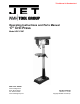
This Manual is Bookmarked Operating Instructions and Parts Manual 17” Drill Press Model JDP-17MF WMH TOOL GROUP 2420 Vantage Drive Elgin, Illinois 60123 Ph.: 800-274-6848 www.wmhtoolgroup.com Part No.
This manual has been prepared for the owner and operators of a JDP-17MF Drill Press. Its purpose, aside from machine operation, is to promote safety through the use of accepted correct operating and maintenance procedures. Completely read the safety and maintenance instructions before operating or servicing the machine. To obtain maximum life and efficiency from your JET Drill Press, and to aid in using the machine safely, read this manual thoroughly and follow instructions carefully.
, WARNING Wear eye protection. Always keep guards in place and in proper operating condition. Do not operate the machine without the guards for any reason. Support workpiece adequately at all times during operation; maintain control of work at all times. This drill press is designed and intended for use by properly trained and experienced personnel only. If you are not familiar with the proper and safe operation of a drill press, do not use until proper training and knowledge has been obtained.
• USE RECOMMENDED ACCESSORIES. The use of accessories and attachments not recommended by JET may cause hazards or risk of injury to persons. • NEVER STAND ON A MACHINE. Serious injury could occur if the machine is tipped. • CHECK DAMAGED PARTS.
Grounding Instructions Caution: This tool must be grounded while in use to protect the operator from electric shock. In the event of a malfunction or breakdown, grounding provides a path of least resistance for electric current to reduce the risk of electric shock. This tool is equipped with an electric cord having an equipment-grounding conductor and a grounding plug. The plug must be plugged into a matching outlet that is properly installed and grounded in accordance with all local codes and ordinances.
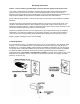
230 Volt Operation If 230V, single phase operation is desired, the following instructions must be followed: 1. Disconnect the machine from the power source. 2. This JET drill press is supplied with four motor leads that are connected for 115V operation, as shown in Figure A. Reconnect these four motor leads for 230V operation, as shown in Figure B. 3. The 115V attachment plug (A), supplied with the drill press, must be replaced with a UL/CSA listed plug suitable for 230V operation (D).
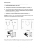
On-Off Switch Padlock Model No. BP-1, Stock No. 709736 To safeguard your machine from unauthorized operation and to avoid accidental starting by young children, the use of a padlock is highly recommended. JET model BP-1 is available from your local authorized JET distributor or by calling WMH Tool Group at 800-274-6848. To lock out an on-off switch: 1. Open the padlock. See Fig. A. 2. Insert through holes in the start button. See Fig. B 3. Close the padlock. 4. Place the key in a safe place.
Specifications: JDP-17MF Stock Number ..................................................................................................................................... 354169 Swing....................................................................................................................................................16-1/2” Type ........................................................................................................................................................
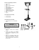
Contents of the Shipping Container 1. 1. 1. 1. 1. 1. 1. 3. 1. 1. 4. 1. 1. Head Assembly Table Column and Bracket Assembly Base Owner’s Manual Warranty Registration Card Chuck and Chuck Key Downfeed Handle Table Bracket Lock Handle Table Bracket Raising Handle M10 x 40 Hex Cap Bolts Arbor Drift Key Tools Supplied for Assembly 1. 3mm Hex Wrench 1. 5mm Hex Wrench Tools Required for Assembly 1.
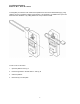
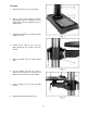
Assembly 1. Place the base (A, Fig. 1) on a level floor. 2. With a 17mm wrench attach the column assembly (B, Fig. 1) to the base (A, Fig. 1) with four M10 x 40 hex cap bolts (C, Fig. 1). Tighten firmly. 3. Thread lock handle (D, Fig. 2) into the table bracket (E, Fig. 2). 4. Loosen the set screw (F, Fig. 3) on the raising handle (G, Fig. 3) with a 3mm hex wrench. 5. Slide the handle onto the table bracket shaft. 6.
9. With the aid of a second person, carefully lift the head onto the column top. Caution: The head assembly is heavy! Use care when lifting onto the column! 3. Place a piece of scrap wood on the table, and lower quill using the down feed handle. 10. Rotate head assembly until sides of the belt cover are parallel with the sides of the base. 4. Rotate spindle to align the key hole in the spindle with the key hole in the quill. 11. Tighten two set screws (A, Fig. 4) with a 5mm wrench until they are snug.
Adjusting the Depth Stop To drill multiple holes at the same preset depth, use the depth stop: 1. Use a pencil to mark the depth the bit will drill into the workpiece (A, Fig. 7). 2. With the drill bit in the chuck, lower down feed handle to advance bit to your mark,see Figure 7. 3. With your other hand, advance the lock nuts (B, Fig. 7) on the depth stop rod until they are snug to the seat (C, Fig. 7). 4. The drill bit will now advance to this point. 5.
Speed & Pulley Chart 13
Return Spring Adjustment The return spring is adjusted at the factory and should not need further adjustment. If adjustment is deemed necessary: 1. Unplug the machine from the power source. 2. Loosen two jam nuts (A, Fig. 9). Do not remove. 3. Firmly hold the coil spring cover (B, Fig. 9). 4. Pull out the cover and rotate until the pin (C, Fig. 9) on the return spring plate engages the next notch in the coil spring cover.
Basic Operation • Always use a back-up piece of scrap wood to cover the table. This protects both the table and the drill bit. • Place material to be drilled in such as way as to come into contact with the left side of the column. This prevents the material from spinning.
Troubleshooting Trouble 1. Drill press will not start. Drill press does not come up to speed. Drill Press vibrates excessively. 2. 3. 4. 1. 2. Probable Cause Drill press unplugged from wall, or motor. Fuse blown, or circuit breaker tripped. Cord damaged. Starting capacitor bad. Extension cord too light or too long. Low current. 1. Stand on uneven surface. 2. Bad belt(s). 1. Incorrect belt tension. 2. Dry spindle. Noisy Operation. 3. Loose spindle pulley. 4. Loose motor pulley. 1. Incorrect Speed.
Parts Breakdown for JDP-17MF 17
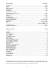
Parts List for JET JDP-17MF Drill Press Index Part No. No. Description Size Qty. 1 ..........10600111 ......................Base ..................................................................... .................................... 1 2A ........12909001A1..................Column and Holder Assy. .................................... .................................... 1 3 ..........TS-1525021 ..................Set Screw............................................................. M10x12 ............
Index Part No. No. Description Size Qty. 61 ........BB-6203Z ......................Ball Bearing.......................................................... .................................... 1 62 ........10606201 ......................Washer................................................................. .................................... 1 63 ........10606301 ......................Lock Nut ............................................................... .................................... 1 64 .....
Index Part No. No. Description Size Qty. 169 ......11316904 ......................Nameplate............................................................ .................................... 1 601 ......TS-1533032 ..................Pan Head Machine Screw ................................... M5x10 ......................... 2 602 ......2504MZC005 ................Tooth Washer ...................................................... .................................... 2 607 ......TS-0720101 ..................
WMH Tool Group 2420 Vantage Drive Elgin, Illinois 60123 Phone: 800-274-6848 www.wmhtoolgroup.