.lET EQUIPMENT & TOOLS OPERATOR'S MANUAL JDP-20VS-1/3 Drill Press (JDP-20VS-3 shown) JET EQUIPMENT& TOOLS,INC. A WMH - Walter Meier Holding Company Po. BOX 1349 Auburn, WA 98071-1349 253-351-6000 Fax 253-939-8001 No.
Important Information 1-YEAR JET offers a one-year limited warranty on this product LIMITED WARRANTY REPLACEMENT PARTS Replacement parts for this tool are available directly form JET Equipment & Tools. To place an order, call 1-800-274-6848. Please have the following information ready: 1. Visa, MasterCard, or Discover Card number 2. Expiration date 3. Part number listed within this manual 4. Shipping address other than a Post Office box.
it WARNING For your own safety, read the operator's manual before operating the drill press. Wear eye protection. Do not wear gloves, neckties, long sleeves, jewelry, or loose clothing that may become caught in moving parts. Long hair must be contained. Clamp the workpiece or brace it against the column to prevent rotation. Use the recommended speed for drill accessories and workpiece materials. . . . . . KEEP GUARDS IN PLACE and in working order. KEEP ALL BODY PARTS AWAY FROM MOVING PARTS.
. . . . . ALWAYS DISCONNECTTHEMACHINEFROMTHEPOWERSOURCEBEFORESERVICING. REDUCE THE RISK OF UNINTENTIONALSTARTING. Make sure the switch is in the off position before plugging in. NEVER STAND ON A MACHINE. Serious injury could occur if the machine tipped or if the drill bit is unintentionally contacted. CHECK DAMAGED PARTS.
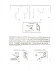
Electrical Instructions Caution: This tool must be grounded while in use to protect the operator from electric shock. Note: The JDP-20VS-1 is rated at 115/230V and comes pre-wired at 230V. The JDP-20VS-3 is rated at 230V and cannot be changed. In the event of a malfunction or breakdown, grounding provides a path of least resistance for electric current to reduce the risk of electric shock. This tool is equipped with an electric cord having an equipment-grounding conductor and a grounding plug.
230Volt 115Volt 3 2 v 3 4 Line Line Line 4 2 Line Fig. C Fig. D Grounded Outlet Box C"".~ Grounding Bla~ longest of the 3 blades Fig. E As received from the factory, the JDP-20VS-1 drill press is ready to run at 230 volt operation (the JDP20VS-3 is 230V and cannot be changed). This drill press, when the wiring is changed to 115 volt, is intended for use on a circuit that has an outlet and a plug that looks the one illustrated in Figure A.
Specifications: JDP-20VS-1 Stock Number... Drilling Capacity Cast Iron (in.) Steel (in.) , Tapping Capacity (in.) Column Capacity (in.) Spindle to Column (maximum - in.) Spindle Travel (in.) Spindle Distance to Table (in.) " Table Size (in.) Number of T-Slots T-Slot Size (in.) T-Slot Centers (in.) Spindle Taper Spindle Speeds Spindle RPM (approx.) Motor 354201 1-1/2 1-1/4 NA 4.
Unpacking and Clean-Up 1. Finish removing the shipping crate. 2. Remove the skid from under the press. 3. Remove the protective coating from all rust protected surfaces with a soft cloth moistened with kerosene or a mild solvent. Do not use acetone, gasoline, or paint thinner. These will damage painted surfaces. 4. To prevent rust, apply a thin coat of paste wax to the table. Installation The drill press must be located in a dry, well lighted area with adequate room on all sides of the machine.
5. Tighten the two head locking bolts (A, Fig. 2). This will hold the head in place until the lock collar can be moved into position. The 2" x 4" can now be safely removed. 6. After the head is set at the desired height, loosen two set screws (8, Fig. 2) on the lock collar. B C 7. Slide the lock collar up the column until it is flush with the head. 8. Firmly tighten two set screw (8, Fig. 2). Fig.
ControlPanel- JDP-20VS-3 High-Low Switch (A, Fig. 5) - the center position is neutral. Turn to the right to select the low motor speed. Turn to the left to select the high motor speed. Drill Tap Switch (8, Fig. 5) - the center position is the off position. Push the switch to the left for the drill function. Push the switch the right for the tap function. A B C D E F Power Indicating Lamp (C, Fig. 5) - indicates power to the main panel when lit. This lamp will only light up in the drill or tap mode.
Adjusting the Depth Stop for Tapping (JDP-20VS-3 only) To adjust the depth stop for tapping, follow the instructions for adjusting the depth stop for drilling. The major differences in the tap mode are two micro-switches. One micro-switch automatically reverses (counter-clockwise) the spindle direction at a predetermined depth. The other micro-switch forwards (clockwise) the direction of the spindle once it is fully retracted.
Drill Speed Chart Use the following-drill speed charts to determine the approximate drill speed for the size bit and type of material to be drilled. Speeds are listed in revolutions per minute. Drill Diameter (in.
JDP-20VS-1/3 Head Assembly 30 3 t(76 6 50 51 1" I 20 ", I I 19 I I 24 I i I 25 19 21 31 I I ! 26 I ~ 27 19 ~ 28 ~ 20 11
JDP-20VS-1/3 Head Assembly Index Part No. No. 1 2 3 4 5 6 7 8 9 10 11 12 13 14 15 16 17 18 19 20 21 22 23 24 25 26 27 28 29 30 31 32 33 34 35 36 37 38 39 40 41 42 43 44 45 46 47 48 70-1507 70-1509 70-1508 70-1516 70-1512 70-1515 70-1515-1 A-632 71-1610 70-1513 70-1901 70-1903 71-1009 71-1001B 70-1026B 70-1019B 70-1020B 70-1022 70-1407B 70-1408 70-1408-1 70-1401B 71-1402B 71-1402-1 71-1004B BB-62062 71-1003B...
JDP-20VS-1/3 Head Assembly (continued) 49 .. 50 .JDP20VS-49 TS-0061041 Screw... Hex Cap BoiL 51 TS-0680051 SpringWasher 52 JDP20VS-52 Washer ... 3/16 x 3/8 7/16 x 1-1/4 7/16 , 13 , , , , ., , ...
JDP-20VS-1/3 Variable Speed Assembly , 11~ ~>-37 ~~ 12$ ~./38 . 39~~~ l 13--@J ~~ 14.'/ ! ~I r 15~1 . 23 9 . -~~y 36~. ~24 , ~~ 10, ~. 22 8 1 ~16 ;/ ~ - -<'" ~17 ~ 0 18/~ . ~i ~19 25 17 . ~34 ~35 20 $-26 4 ~27 $--28 21 32~.. 31~ ~--6 ~26 ~29 I ~F ~30 I I 14 ",.'~ 1S:.
JDP-20VS-1/3 Variable Speed Assembly 1 2 3 4 5 6 7 8 9 70-1206 70-1211 70-1023 70-1210 70-1024 70-1212 70-1505 70-1502 70-1504 V-Belt Upper MotorPulley MotorPulley Sleeve LowerMotorPulley Pulley Spring Spring Housing Hinge Pin Spindle ControlSupport Support Swivel VB-1926V427 ...
16 16
JDP-20VS-1/3 Column, Table, and Base Assembly 1 2 3 4 5 6 7 8 9 10 11 12., 13 14 15 16 17 18 19 20 .. 21 22 23 24 25 26 27 28 29 30 31 32 33 34 70-3008 70-1306 BB-51102 ... 70-1302 71-1301 70-1305 71-1302 70-1303 71-3003 71-3005 70-1008 71-2001 71-2005 71-2004 71-2003 71-2002 70-2005 70-2004 70-2006 :.71-3001 .. TS-0272021 SB-3/8 TS-0561021 TS-0270091 '''''''''''''''''''''' JDP20YS-25 TS-0561031 """"""""""" TS-0680041 JDP20YS-28 TS-0267021 JDP20YS-30A TS-0208081 JDP20YS-32B TS-0208021 TS-0680031 ..
JDP-20VS-1/3 Depth Stop and Control Box Assembly 18
JDP-20VS Depth Stop and Control Box Assembly 1 On-OffSwitch (JDP-120VS-1 only) 3 4 71-1601 70-17630 71-1704 71-1703 5 6 70-1611B 70-1612B Scale , StrokeStop Bracket 7 8 9 10 11 12 13 14 71-1706 50-1610 70-1606B 50-1606 50-1615 70-1404B.. 70-141OB 71-1609B Tapping Control Nut Depth Indicator Screw Micro-Dial Screw Support Spring Spring Protector Bracket 1 1 1 1 1 2 2 1 15 .50-1607 Knob 1 16 17 18 19 20 21 22 .. 23 24 25 ...
Electrical (JDP- 20VS-3) Panel Components 10 6 1 Fu 2A 9 8 7 r I I 0 0 V. 1 24V. 1 1- I r I 220V 440V [£] . CL-4L I I I . 1 380V. Transformer 8 r.0 1 [ill C-11 L 9 15.
Electrical Panel Components (JDP-20VS-3 only) 1 2 3 E-101 E-102 E-103 4 E-104 5 6 7 8 9 10 11 E-106 E-013 E-014 E-111 E-016 E-015 E-110 12 """" E-001 ""'"'''''''''''''''' High-Low Switch Start Button Drill-Tap Switch 1 1 ; ReturnSwitch ; :': : Emergency Stop Switch Fuse(2AMP) Fuse Seat Transformer Magnetic Starter (CL-4L) Magnetic Starter (C-11L) Terminal Relay Light(24v) . ..; 1 1 1 1 ,....,.1 1 '.1 1 1 '.
R s T TC220V MR MF AC24V a 2A I\J I\J T1 51 R1 4P18P CS W 2 V2 U2 W 1 V1 U1 ~ I 0 EMG Stop 6 IJ C Start , 6 I I S I I Drill 0- .I Off TAP D 3 .. 0 . ~ ( J r--12 LS 1 Return 0--2.2...
/