Operating Instructions and Parts Manual 12" Sliding Dual Bevel Compound Miter Saw Benchtop Series – Model No. JMS-12SCMS R C US 174315 For serial no. 10070329 and higher WALTER MEIER (Manufacturing) Inc. 427 New Sanford Road LaVergne, Tennessee 37086 Ph.: 800-274-6848 www.waltermeier.com Part No. M-707120 Revision B 08/2010 Copyright © 2010 Walter Meier (Manufacturing) Inc.
Warranty and Service Walter Meier (Manufacturing) Inc., warrants every product it sells. If one of our tools needs service or repair, one of our Authorized Service Centers located throughout the United States can give you quick service. In most cases, any of these Walter Meier Authorized Service Centers can authorize warranty repair, assist you in obtaining parts, or perform routine maintenance and major repair on your JET ® tools.
Table of Contents Warranty and Service................................................................................................................................2 Table of Contents .....................................................................................................................................3 Warnings..................................................................................................................................................5 Compound Miter Saw Safety .........
Auxiliary Wood Fence .......................................................................................................................... 26 Cutting Base Molding........................................................................................................................... 27 Bevel/Miter Settings............................................................................................................................. 27 Removing the Blade ..................................................
Warnings 1. Read and understand the entire owners' manual before attempting assembly or operation. 2. Read and understand the warnings posted on the machine and in this manual. Failure to comply with all of these warnings may cause serious injury. 3. Replace the warning labels if they become obscured or removed. 4. This saw is designed and intended for use by properly trained and experienced personnel only.
23. Give your work undivided attention. Looking around, carrying on a conversation and “horse-play” are careless acts that can result in serious injury. 24. Maintain a balanced stance at all times so that you do not fall or lean against the blade or other moving parts. Do not overreach or use excessive force to perform any machine operation. 25. Use the right tool at the correct speed and feed rate. Do not force a tool or attachment to do a job for which it was not designed.
Compound Miter Saw Safety Specific safety instructions for this compound miter saw 1. Do not operate the miter saw until it is completely assembled and installed according to these instructions. 2. If you are not thoroughly familiar with the operation of miter saws, seek guidance from your supervisor, instructor or other qualified person. 3. Always hold the work firmly against the fence and table. 4. Do not perform any operation free hand (use clamp wherever possible). 5.
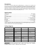
Introduction This manual is provided by Walter Meier (Manufacturing) Inc., covering the safe operation and maintenance procedures for the JET Model JMS-12SCMS Dual Bevel Sliding Compound Miter Saw with laser. This manual contains instructions on installation, safety precautions, general operating procedures, maintenance instructions and parts breakdown. This machine has been designed and constructed to provide years of trouble free operation if used in accordance with instructions set forth in this manual.
Electrical Extension Cords Make sure your extension cord is in good condition. When using an extension cord, be sure to use one heavy enough to carry the current your machine will draw. An undersized cord will cause a drop in the line voltage resulting in power loss and overheating. The table below shows the correct size to use depending on the cord length and nameplate ampere rating. If in doubt, use the next heavier gauge. Remember, the smaller the gauge number, the heavier the cord.
Features 10
Shipping Contents Unpacking 1. Remove the contents from the shipping container. 2. Compare the contents of the shipping container with the list found below. Make certain that all items are accounted for before discarding any packing material. Report any shortages or damage to your JET distributor.
Assembly Unlocking the Slide Carriage Loosen the slide carriage lock knob (A). When transporting or storing the miter saw, the slide carriage (B) should always be locked in position. Releasing the Cutting Head Figure 1 When not in use, lock the cutting head in the down position. Failure to comply can cause serious injury or damage equipment. Unlocking 1. Push down on the switch handle (page 10). 2. Pull out the hold-down latch (A, Fig. 2). 3. Raise the cutting head to the up position.
Installing the Safety Hold-down Clamp 1. Place the hold-down clamp assembly (A, Fig. 4) in a mounting hole located behind the right or left fence (B, C). 2. Thread the hold-down clamp knob (D) into the hole located at the rear of the saw base. 3. Tighten the hold-down clamp knob (D). Figure 4 Power Cord Storage Clips The slide carriage has two clips on the rear for cord storage when the machine is not in use. To assemble: Attach each storage clip (A, Fig.
Table Inserts For portable use: Always unplug the saw to avoid accidental starting. Failure to comply may cause serious injury! Place the saw on a 3/4 in. thick piece of plywood and bolt the base securely to the plywood using the mounting holes on the base. Mounting hardware is not included and must be purchased separately. ! Remove table insert to remove all small pieces of debris from the table cavity before performing any cuts.
Installing Blade Important: This diameter blade. machine requires a 12-inch Unplug the miter saw before changing and/or installing the blade. Referring to Figure 7: 1. Install a 12 in. blade with a 5/8 in. arbor (or a 1 in. arbor with a 5/8 in. reducer) making sure the rotation arrow on the blade matches the clockwise rotation arrow on the upper guard, and the blade teeth are pointing downward. 2. Place the arbor collar (G) against the blade and on the arbor.
Adjustments Before attempting any adjustments – To avoid injury from unexpected starting or electrical shock make sure the trigger is released and remove the power cord from the power source. Failure to comply may cause serious injury! A Note: Your miter saw was adjusted at the factory. However, during shipment slight misalignment may have occurred. Check the following settings and adjust if necessary prior to using this miter saw. Figure 8 B Bevel Stop Adjustments B 90°(0°) Bevel Adjustment 1.
2. Loosen the bevel lock handle (A, Fig. 8) and tilt the cutting arm completely to the left (Figure 11). 3. Using a combination square, check to see if the blade is 45° to the table. 4. To adjust, tilt the cutting arm to zero degrees, loosen the lock nut (B, Fig. 12) and turn the stop bolt (A, Fig. 12) in or out accordingly. 5. Tilt the cutting arm back to the left and recheck alignment. Figure 12 6. Repeat steps 1–4 if necessary until the blade is 45° to the table, then tighten the lock nut (B, Fig.
Miter Angle The sliding compound miter saw scale can be easily read, showing miter angles from 0° to 45° to the left, and 0° to 60° to the right. The miter saw table has ten of the most common angle settings with positive stops at 0°, 15°, 22.5°, 31.6°, and 45° and 60° right. These positive stops position the blade at the desired angle quickly and accurately. Follow the process below for quickest and most accurate adjustments. Referring to Figure 16: 1.
Positive Stop Miter Angle Adjustment Referring to Figure 19: 1. Unlock the miter table by lifting up on the quickcam miter table lock (A). 2. Raise the positive stop locking lever (C) up; at the same time grasp the miter handle (B) and rotate the miter table left or right to the desired angle. 3. Release the positive stop locking lever (C) and set the miter at the desired angle making sure the lever snaps into place. Note: There are ten positive stops into which the lever will lock. 4.
Presetting the Cutting Depth Laser Beam The depth of cut can be preset for even and repetitive shallow cuts. The laser is turned on with a switch located on the saw handle (C, Fig. 23). When left on indefinitely, a sensor will turn the laser off after 20 minutes. The switch must be reset (turned off for two seconds, then on again) to restart. Referring to Figure 21: 1. Pull hold-down latch (C) out. 2. Flip the stop plate (A) counterclockwise to the left.
Operation Before attempting any operation with your miter saw, make sure that you have read and thoroughly understand the warnings contained on pages 5-6 and the Compound Miter Saw Safety section on page 7. Failure to comply may result in serious injury! Starting a cut 1. Place hands at least 8-3/4 in. away from the path of the blade. 2. Hold workpiece firmly against the fence to prevent movement toward the blade. C A B 3. Bring the saw blade down to the workpiece to see the cutting path of the blade. 4.
Sliding Fence The sliding fence must be extended to the left or right when making bevel cuts. Failure to comply may cause serious injury! Failure to extend the sliding fence will not allow enough space for the blade to pass through. This could result in serious injury. At extreme miter or bevel angles the saw blade may also contact the fence resulting in damage to equipment as well as personal injury.
Miter Cut Referring to Figure 26: The sliding compound miter saw has ten positive miter stop indents (A) located on the saw base. The stops represent the following miter cut angles: 0, 15, 22.5, 31.6 and 45 degrees left and right, and 60° right. To make a miter cut: 1. Unlock the miter table by lifting up on the quickcam miter table lock (E). 2. Raise the positive stop locking lever (C) up, at the same time grasp the miter handle (D) and rotate the miter table left or right to the desired angle. 3.
33.9° Bevel Detent Pin for Crown Moldings Note: A bevel detent pin is incorporated into this machine for quick bevel adjustments when the desired bevel angle is 33.9°. Referring to Figure 27 (except where indicated): 1. Push the bevel detent stop pin (E) in. 2. Loosen the bevel lock handle (A). 3. Rotate the cutting head (D, Fig. 28) until the bevel detent pin (E) stops the bevel angle at 33.9° on the bevel scale (F). 4. Tighten the bevel lock handle (A) before you make your cut.
4. Position the workpiece on the table and against the fence. Use a hold-down clamp (E) attached to the base, whenever possible. 5. Pull the trigger (A), turning on the saw. Lower the blade by pushing the handle (B) down into the workpiece with slow and even pressure. 6. When the cut is complete, release the switch and allow the blade to stop before raising the cutting head assembly.
Cutting Bowed Material Always unplug the saw when removing small pieces of debris. Failure to comply may cause serious injury! Referring to Figure 31: 1. Position a curved workpiece (C) against the fence (B). 2. Secure the curved workpiece with a clamping device (A). Cutting a curved workpiece without the support of the fence and clamping device could result in personal injury. Figure 31 Rough Cutting a Dado 1.
Cutting Base Molding Crown Molding Base moldings and many other moldings can be cut on a compound miter saw. The setup of the saw depends on molding characteristics and application. Perform practice cuts on scrap material to achieve best results: Your compound miter saw is suited for the difficult task of cutting crown molding. To fit properly, crown molding must be compound-mitered with extreme accuracy.
Crown Molding Chart Compound miter saw miter and bevel angle settings, wall to crown molding angles 52/38º Crown Molding Angle Between Walls 67 68 69 70 71 72 73 74 75 76 77 78 79 80 81 82 83 84 85 86 87 88 89 90 91 92 93 94 95 96 97 98 99 100 101 102 103 104 105 106 107 108 109 110 111 112 113 114 115 116 117 118 119 120 121 122 123 45/45º Crown Molding 0Miter 0Setting 0Bevel 0Setting 0Miter 0Setting 0Bevel 0Setting 42.93 42.39 41.85 41.32 40.79 40.28 39.76 39.25 38.74 38.24 37.74 37.24 36.75 36.
Maintenance Lower Blade Guard Do not use the saw without the lower blade guard. The lower blade guard is attached to the saw for your protection. Should the lower guard become damaged, do not use the saw until the damaged guard has been replaced. Develop a regular check to make sure the lower guard is working properly. Clean the lower guard of any dust or buildup with a damp cloth. To avoid injury while performing maintenance, always unplug the power cord before working on the saw.
Troubleshooting – Motor Trouble Brake does not stop blade within 10 seconds. Probable Cause Remedy Motor brushes not sealed or lightly sticking. Inspect/clean/replace brushes. Motor brake overheated from use of defective or wrong size blade or rapid ON/OFF cycling. See MAINTENANCE section. Arbor bolt loose. Use a recommended blade. Let cool down. See Removing or Installing the Blade section. Brushes cracked, damaged, etc. Retighten. See Removing or Installing the Blade section. Other.
Parts Ordering Replacement Parts To order parts or reach our service department, call 1-800-274-6848 Monday through Friday (see our website for business hours, www.waltermeier.com). Having the Model Number and Serial Number of your machine available when you call will allow us to serve you quickly and accurately. Parts List Note: Parts without part numbers are for reference only and cannot be purchased individually. Index No. Part No. Description Size Qty 1 .............. JMS10SCMS-1 ........
Parts List Index No. Part No. Description Size Qty 50 ............ TS-0680041 ............Flat Washer......................................................3/8 ............................. 1 51 ............ JMS10SCMS-36 ......External Tooth Lock Washer..............................M5 ............................. 2 52 ............ JMS10SCMS-37 ......Wave Washer...................................................WW-8 ........................ 2 53 ............ JMS12SCMS-53 ......Wave Washer................
Parts List Index No. Part No. Description Size Qty 108 .......... JMS10SCMS-210 ....Cable Clamp ....................................................1/8” ............................ 1 109 .......... JMS10SCMS-87 ......Cable Clamp ....................................................3/8” ............................ 1 110 .......... JMS10SCMS-88 ......Terminal............................................................................................. 2 111 .......... JMS12SCMS-111 ....Locking Cable Tie .
Parts List Index No. Part No. Description Size Qty 166 .......... JMS12SCMS-166 ....Bearing Protector................................................................................ 1 167 .......... JMS10SCMS-113 ....Shaft .................................................................................................. 1 168 .......... JMS12SCMS-168 ....Cord Clamp ........................................................................................ 1 169 .......... JMS12SCMS-169 ....Torsion Spring .
Parts List Index No. Part No. Description Size Qty 223 .......... JMS12SCMS-223 ....Swivel Support Assembly .................................................................... 1 224 .......... JMS12SCMS-224 ....Guard Plate ........................................................................................ 1 225 .......... JMS12SCMS-225 ....Saw Blade........................................................12”x60Tx1” Arbor........ 1 226 .......... JMS10SCMS-194 ....Clamp Hold Down Assembly ..........
Assembly Drawing 36
Assembly Drawing 37
Assembly Drawing 38
Wiring Diagram 39
WALTER MEIER (Manufacturing) Inc. 427 New Sanford Road LaVergne, Tennessee 37086 Phone: 800-274-6848 www.waltermeier.