This manual is bookmarked Operating Instructions and Parts Manual Planer Model: JWP-208 WMH TOOL GROUP 2420 Vantage Drive Elgin, Illinois 60123 Ph.: 800-274-6848 www.wmhtoolgroup.com Part No.
Warranty and Service WMH Tool Group, Inc., warrants every product it sells. If one of our tools needs service or repair, one of our Authorized Service Centers located throughout the United States can give you quick service. In most cases, any of these WMH Tool Group Authorized Service Centers can authorize warranty repair, assist you in obtaining parts, or perform routine maintenance and major repair on your JET® tools. For the name of an Authorized Service Center in your area call 1-800-274-6848.
Table of Contents Table of Contents.......................................................................................................................................... 3 Warnings ....................................................................................................................................................... 4 Features ........................................................................................................................................................
Warnings Read the manual. Always read the owner’s manual carefully before attempting to use the machine. Know the limitations and hazards associated with the use of this planer. Installation. If mounting machine to the floor, use high quality anchor bolts through the mounting holes on the base. If using a mobile base, be sure to lock the wheels. Eye protection. Always wear approved safety goggles, glasses, or a face shield when operating this machine.
Safety Decals Familiarize yourself with the location and content of these decals on your planer. ! 1. 2. 3. 4. 5. 6. Read instruction manual before operating machine. Do not operate without all guards properly installed. Remove or fasten loose articles of clothing such as neckties, etc. Contain long hair. Remove jewelry such as finger rings, watches, bracelets, etc. Use approved safety glasses and/or face shield to protect eyes, and use other personal safety equipment as required. Do not wear gloves. 7.
Features Fig. 2 Specifications Model No. ........................................................................... JWP-208-1........................................ JWP-208-3 Stock No................................................................................... 708528.............................................. 708584 Table Area (D x W/in.)........................................................ 25-3/4 x 20........................................ 25-3/4 x 20 Maximum Planing (W/in.) ..............
Receiving Carefully unpack the planer and any loose items from the wood crate and inspect for damage. Any damage should be reported immediately to your distributor and shipping agent. Before proceeding further, read your manual thoroughly to familiarize yourself with proper assembly, maintenance and safety procedures. Remove the screws that hold the planer to the shipping skid.
Handwheel 1. Remove the nut and washer from the gearbox shaft, and place the handwheel onto the shaft (Fig. 5), making sure it is oriented so the handwheel slips over the key. 2. Place flat washer and hex nut on shaft and tighten with wrench. 3. Mount the handle in the threaded hole in the handwheel, and tighten with a wrench placed over the flat on the handle. Figure 5 Table Extension Rollers Mount the table extension rollers to the table using the provided hex cap screws and washers (A, Fig. 6).
Electrical Connections Electrical connections must be made by a qualified electrician in compliance with all relevant codes. The machine must be properly grounded to help prevent electrical shock and possible fatal injury. A power plug is not provided with the 208 planer. You may either connect one or "hard-wire" the machine directly to your electrical panel provided there is a disconnect near the machine. Consult the wiring diagrams on pages 32-33 for further clarification of wiring setup.
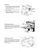
2. Check belt tension. Proper tension is obtained when there is approximately 1/4” deflection of the center span of the pulleys using light finger pressure (Fig. 10). Figure 10 3. If adjustment of belt tension is necessary, loosen one pair of hex nuts (E & F, Fig. 11) and turn the other pair to raise or lower the motor plate. Re-tighten nuts. Figure 11 Table Rollers Overview Your planer is supplied with two table rollers (A, Fig.
The table rollers are factory set for average planing and are parallel to the table surface. If you desire to adjust the table rollers higher or lower, proceed as follows: Figure 13 1. Disconnect machine from power source. 2. Lay a straight edge (B, Fig. 14) across both rollers. 3. On one side of the table, loosen the screws (C, Fig. 14) with a hex wrench, and turn the eccentric shafts (D, Fig. 14) to raise or lower the rollers. 4. When the proper height is achieved, tighten screws (C, Fig. 14). 5.
Adjusting Depth of Cut The cutting depth scale (A, Fig. 16) is a combination inch/metric scale with a cutting range from 0 to 8” (204mm). The distance of upward or downward movement is controlled by the handwheel (B, Fig. 16). One revolution of the handwheel is .059” (1.5mm). Before moving the table up or down, loosen the lock nuts (C, Fig. 16). After obtaining the proper table position, tighten the lock nuts (C, Fig. 16). Always tighten the lock nuts before operating the planer.
lightly backing out the six locking screws (F, Fig. 19) against the slot. NOTE: At this time, only tighten the knife in the slot just enough to hold knife in position. 6. If additional knives must be reset, repeat step 5. 7. After all four knives are set with screws just snug, back out and tighten the six locking screws (F, Fig. 19 & 20), against the slot starting with the end screws first, then the center screws, until the knife is securely held in the cutterhead.
the same manner. 11. After all four knives are set with the screws just snug, back out and tighten the six screws (F) against the slot starting with the end screws first and then the center screws until the knife is securely held in the cutterhead. Tighten the remaining three knives in the same manner. After replacing and checking knives, CHECK AGAIN carefully. Make certain the direction of knives is correct and all twenty-four locking screws are tightened securely.
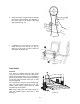
Know the Transmitting Rollers of Your Planer A – Anti-Kickback Fingers B – Infeed Roller C – Chipbreaker D – Cutterhead D – Pressure Bar E – Outfeed Roller The infeed roller (B, Fig. 23) and outfeed roller (F, Fig. 23) are those parts of your planer that feed the stock while it is being planed.
Figure 25 Height of Infeed Roller, Chipbreaker, Pressure Bar & Outfeed Roller The infeed roller, chipbreaker, pressure bar and outfeed roller are adjusted at the factory. The infeed roller and the chipbreaker should be set at 0.004” (0.1mm) below the cutting circle; and the outfeed roller should be set at 0.02” (0.5mm) below the cutting circle. See Fig. 25. If an adjustment to the infeed roller, chipbreaker, pressure bar or outfeed roller is necessary, use the following steps as an example of procedure.
Feed Speed Control Your machine is equipped with a spiral, serrated infeed roller and a solid outfeed roller. When the feed rollers are engaged, they turn to feed the stock. The feed rollers slow automatically when the machine is under heavy load for best planing in all conditions. The feed rollers are driven by chains (A, Fig. 28) and sprockets (B, Fig. 28) which take power directly from the cutterhead through the oil bath gear box (C, Fig. 28). The gear box has two feed speeds.
Maintenance Lubrication Periodic or regular inspections are required to ensure that the machine is in proper adjustment, that all screws are tight, that belts are in good condition, that dust has not accumulated in the electrical enclosures, and that there are no worn or loose electrical connections. The bearings on the cutterhead are factory lubricated and sealed for life – no lubrication required. The lubricant in the gearbox must be replaced every 2,500 hours.
Figure 32 Figure 34 Figure 35 Figure 33 19
Troubleshooting Operating Problems Problem Snipe. Note: Snipe can be minimized but not eliminated. Fuzzy Grain Torn Grain Rough/Raised Grain Rounded, glossy surface Poor feeding of lumber Possible Cause Solution Table rollers not set properly. Adjust rollers to proper height. Inadequate support of long boards. Support long boards with extension rollers. Uneven feed roller pressure front to back. Adjust feed roller tension. Dull Knives Sharpen knives. Lumber not butter properly.
Mechanical and Electrical Problems Problem Possible Cause Solution Uneven depth of cut side to side. Knife projection. Adjust knife projection. Cutterhead not level with bed. Level bed. Board thickness does not match depth of cut scale. Depth of cut scale incorrect. Adjust depth of cut scale. Chain jumping. Inadequate tension. Adjust chain tension. Sprockets misaligned. Align sprockets. Sprockets worn. Replace sprockets. No incoming power. Verify unit is connected to power.
Problem Possible Cause Solution is correct, you have a motor problem. Motor failure. If electrical motor is suspect, you have two options: Have a qualified electrician test the motor for function or remove the motor and take it to a quality electric motor repair shop and have it tested. Miswiring of the unit. Double check to confirm all electrical connections are correct and properly tight. The electrical connections other than the motor are pre-assembled and tested at the factory.
Head Assembly – Parts List Index Part No. Description Size Qty 12 .............BB-6206ZZ...............Ball Bearing.......................................................... 6206ZZ........................ 1 13 .............JWP208-013 ............Key ....................................................................... 8 x 8 x 36 .................... 1 14 .............6292630 ...................Pulley ................................................................... .................................
Head Assembly – Parts List Index Part No. Description Size Qty 68 .............6292684 ...................Handle.................................................................. .................................... 1 69 .............JWP208-069 ............Scale .................................................................... .................................... 1 70 .............JWP208-070 ............Machine Screw .................................................... M5 x 10 ......................
Head Assembly – Exploded View 25
Table and Roller – Parts and Assembly Index Part No. Description Size Qty 1 ...............JWP208-201 ............Middle Table......................................................... .................................... 1 2 ...............6292722 ...................Roller.................................................................... .................................... 2 3 ...............BB-6201ZZ...............Ball Bearing.......................................................... 6201ZZ........
Stand and Motor – Parts and Assembly Index Part No. Description Size Qty 1 ...............JWP208-401 ............Stand.................................................................... .................................... 1 2 ...............JWP208-402 ............Cover.................................................................... .................................... 2 3 ...............TS-2286201 .............Flat Head Machine Screw.................................... M6 x 20 ...................
Base and Column – Parts List Index Part No. Description Size Qty 1 ...............JWP208-301 ............Base ..................................................................... .................................... 1 2 ...............TS-1525021 .............Set Screw............................................................. M10 x 12 ..................... 8 3 ...............JWP208-303 ............Column................................................................. ...............................
Base and Column – Assembly 29
Gearbox – Parts List Index Part No. Description Size Qty 1 ...............JWP208-501 ............Gear Box .............................................................. .................................... 1 2 ...............OS-28408.................Oil Seal................................................................. .................................... 1 3 ...............BB-6204ZZ...............Ball Bearing.......................................................... 6204ZZ........................
Gearbox – Assembly 31
Wiring Diagrams 230V 3HP Single Phase 32
230V 5HP Three Phase 33
460V 5HP Three Phase 34
Notes 35
WMH TOOL GROUP 2420 Vantage Drive Elgin, IL 60123 Ph: 800-274-6848 www.wmhtoolgroup.