
Operating Instructions Planer JWP-208


12
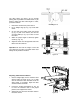
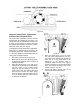
Adjusting Depth of Cut
The cutting depth scale (A, Fig. 16) is a
combination inch/metric scale with a cutting range
from 0 to 8” (204mm). The distance of upward or
downward movement is controlled by the
handwheel (B, Fig. 16). One revolution of the
handwheel is .059” (1.5mm). Before moving the
table up or down, loosen the lock nuts (C, Fig. 16).
After obtaining the proper table position, tighten
the lock nuts (C, Fig. 16).
Always tighten the lock nuts
before operating the planer.
Cutterhead Adjustment
Overview
Although your planer was carefully adjusted at the
factory, it should be checked before being put into
operation. Any inaccuracies due to rough handling
in transit can easily be corrected by following
these directions.
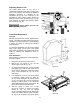
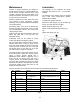
To check the adjustments you will need a straight
edge, feeler gauge, and a home made gauge
block made of hardwood. This gauge block can be
made by following the dimensions shown in
Figure 17.
Knife Adjustment
When checking or adjusting the cutterhead knives,
proceed as follows:
1. Disconnect machine from power source.
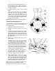
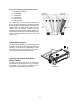
2. Remove the six screws (A, Fig. 18) and
remove upper cover (B, Fig. 18).
3. To check and adjust knives, use the provided
knife gauge (Fig. 19 & 20) and check all four
knives. Knives should just contact the bottom
of the center protrusion (D, Fig. 19) of the
knife gauge.
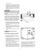
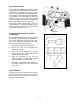
4. If an adjustment to one or more of the knives
is necessary, slightly loosen the knife gib
(E, Fig. 19) by turning the six locking screws
(F, Fig. 19) into the gib. Turn the screws just
enough to relieve stress in the cutterhead
without disturbing the setting of the knives. Do
this for all four knives at the same time.
5. With the gauge in place over a knife
(G, Fig. 19) continue to loosen the locking
screws (F, Fig. 19) until the springs
(H, Fig. 19) begin raising the knife. When knife
comes into contact with the center protrusion
(D, Fig. 19) of the gauge, snug up the gib by
Figure 16
Figure 17
Figure 18