
Operating Instructions Planer JWP-208


14
the same manner.
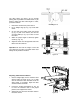
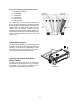
11. After all four knives are set with the screws
just snug, back out and tighten the six screws
(F) against the slot starting with the end
screws first and then the center screws until
the knife is securely held in the cutterhead.
Tighten the remaining three knives in the
same manner.
After replacing and checking
knives, CHECK AGAIN carefully. Make certain
the direction of knives is correct and all
twenty-four locking screws are tightened
securely.
Checking Work Table Parallel to Cutterhead
The work table is set parallel to the cutterhead at
the factory and no further adjustment should be
needed. If your machine is planing a taper, first
check to see if the knives are set properly in the
cutterhead. Then check to see if the work table is
set parallel to the cutterhead. Proceed as follows:
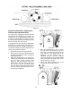
1. Disconnect machine from power source.
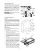
2. Place the gauge block (A, Fig. 21) on the work
table directly under front edge of head casting
(B, Fig. 21). Make slight contact by gently
raising table.
3. Move the gauge block to opposite end of
working table. NOTE: Distance from the
working table to edge of the head casting
should be the same.
4. Check the back of the work table in the same
manner.
Adjusting Work Table Parallel to
Cutterhead
If the work table is not parallel to the cutterhead,
perform the adjustment procedure as follows:
1. Disconnect the machine from power source.
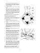
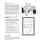
2. Tilt planer on its side to expose underside of
base, as shown in Fig. 22.
3. Remove bolt (A, Fig. 22) and loosen bolt (B,
Fig. 22) which will allow you to move the idler
sprocket assembly (C, Fig. 22) far enough to
release tension on the chain.
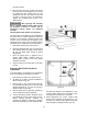
4. Remove chain from the particular sprocket on
corner of base that must be adjusted.
5. Turn the sprocket by hand to bring that corner
into adjustment with the other three corners.
NOTE: Turning sprocket clockwise will
increase the distance between the working
table and headcasting; counter-clockwise will
Figure 21
Figure 22
decrease the distance. This adjustment is very
sensitive and it should not be necessary to turn
the sprocket more than one or two teeth.
6. When adjustments are correct, replace chain
around corner sprocket, slide sprocket (C, Fig.
22) back to re-tension chain, tighten bolt (B, Fig.
22) and replace and tighten bolt (A, Fig. 22).