
Product Manual

16
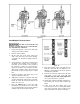
12. It is recommended that the first few lifts be
limited to no more than 25-50% of the rated
load. Inspect chain for twist before placing
hoist into routine service.
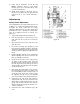
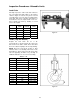
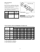
Brake Adjustment
The normal gap between the armature and the iron
core is from 0.5mm to 1.0mm. If the gap is out of
the range of 0.5mm to 1.0mm, it must be adjusted
as follows (see Figure 20):
1. Disconnect hoist from power source.
2. Remove the gear side cover.
3. Remove the locking plate (H) by unscrewing
the four screws (J).
4. Insert a 0.5mm spacer between the iron core
(K) and the armature (B).
5. Tighten the four nuts (G) by an equal amount
one by one. The gap is now adjusted to
0.5mm.
6. Release the four nuts (G) by 1/6 of a turn and
remove the spacer. Re-tighten each of the
nuts by 1/6 of a turn.
7. Re-position the locking plate (H) and install the
four screws (J).
8. Re-install gear side cover.
NOTE: When adjusting the brake, if the brake pad
is found deformed, the glue has failed, or the lining
is severely worn, the brake pad should be
replaced. See page 19.
Figure 20