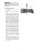
This .pdf document is bookmarked Operation and Maintenance Instructions Belt Drive Bench Lathe, 13x40-inch Model BDB-1340A (shown with optional 321443AK stand) For Parts List and Electrical Diagrams, see document M-321357A JET 427 New Sanford Road LaVergne, Tennessee 37086 Ph.: 800-274-6848 www.jettools.com Part No.
Warranty and Service JET warrants every product it sells against manufacturers’ defects. If one of our tools needs service or repair, please contact Technical Service by calling 1-800-274-6846, 8AM to 5PM CST, Monday through Friday. Warranty Period The general warranty lasts for the time period specified in the literature included with your product or on the official JET branded website. • JET products carry a limited warranty which varies in duration based upon the product.
Table of Contents Warranty and Service .............................................................................................................................. 2 Table of Contents .................................................................................................................................... 3 Warning................................................................................................................................................... 3 Specifications ...................
11. Do not place hands near the chuck while the machine is operating. 12. Make all machine adjustments or maintenance with the machine unplugged from the power source. 13. Remove adjusting keys and wrenches. Form a habit of checking to see that keys and adjusting wrenches are removed from the machine before turning it on. 14. Some dust created by power sanding, sawing, grinding, drilling and other construction activities contains chemicals known to cause cancer, birth defects or other reproductive harm.
Specifications Model Number ........................................................................................................................ BDB-1340A Stock Number.............................................................................................................................. 321360A Capacities: Swing Over Bed ................................................................................................................................... 13" Swing Over Cross Slide ....................
Dimensions of optional stand (p/n 321443AK) To purchase this optional stand for the BDB-1340A Lathe, contact your dealer or call JET customer service.
Machine is heavy! Use an appropriate lifting device and use extreme caution when moving the machine to its final location. Failure to comply may cause serious injury. Uncrating and Clean-Up 1. Finish removing the wooden crate from around the lathe. 2. Unbolt the lathe from the shipping crate bottom. 3. Choose a location for the lathe that is dry, has good lighting, and has enough room to be able to service the lathe on all four sides. Figure 3 4.
Chuck Preparation (Three Jaw) Read and understand all directions for chuck preparation! Failure to comply may cause serious injury and/or damage to the lathe! Note: Before removing the chuck from the spindle, place a way board across the bedways under the chuck. 1. Support the chuck while turning three camlocks 1/4 turn counter-clockwise with the chuck key which is included in the tool box. Figure 4 2. Carefully remove the chuck from the spindle and place on an adequate work surface. 3.
Lubrication Lathe must be serviced at all lubrication points and all reservoirs filled to operating level before the lathe is placed into service. Failure to comply may cause serious damage to the lathe. 1. Headstock - Oil must be up to indicator mark in both oil sight glasses (A, Fig. 5). Top off with Mobil DTE® Oil Heavy Medium. The headstock should be drained and refilled after the first three months of operation. Then, change oil in the headstock annually.
5. Apron - Oil must be up to indicator mark in oil sight glass (A, Fig. 8). Top off with Mobil DTE® Oil Heavy Medium. Fill by removing oil plug (C, Fig. 8). After the first three months of operation, drain oil completely (drain is on the bottom of the apron) and refill with Mobil DTE® Oil Heavy Medium, at a level equivalent to the indicator line. Then, change oil annually. 6. Feed Selector - Lubricate ball oiler (B, Fig. 8) once daily with Mobil DTE® Oil Heavy Medium. 7.
Electrical Connections All electrical connections must be completed by a qualified electrician and must comply with all relevant codes. Failure to comply may cause serious injury and/or damage to the machinery and property. The BDB-1340A bench lathe is rated at 2HP, 1PH, 230V only. Confirm that power available at the lathe's location is the same rating as the lathe. Figure 11 Make sure the lathe is properly grounded. General Description Lathe Bed The lathe bed (A, Fig.
Apron The apron (A, Fig. 13) is mounted to the carriage. In the apron a half nut is fitted. The half nut gibs can be adjusted from the outside. The half nut is engaged by use of a lever. Quick travel of the apron is accomplished by means of a bed-mounted rack and pinion, operated by a hand wheel on the front of the apron. Tailstock The tailstock (B, Fig. 13) slides on a v-way and can be locked at any location by a clamping lever. The tailstock has a heavy-duty spindle with a Morse Taper #3.
Controls 1. Main On-Off Switch (A, Fig. 14) – Power is off in the “0” position and on in the “I” position. 2. Feed Direction Selector (B, Fig. 15) – Arrows above the handle indicate saddle travel direction when the chuck is rotating in the forward direction or counter-clockwise as viewed from the front of the chuck. 3. Feed Rod/Leadscrew Selector (C, Fig. 15) – Use knob and lever to activate leadscrew and feed rod. Figure 14 4. Belt Tensioning Handle (D, Fig.
11. Longitudinal Traverse Handwheel (A, Fig. 17) – Rotate handwheel clockwise to move the apron assembly toward the tailstock (right). Rotate the wheel counter-clockwise to move the apron assembly toward the headstock (left). 12. Feed Selector (B, Fig. 17) – Push lever to the left and down to activate the crossfeed function. Pull lever to the right and up to activate the longitudinal function. 13. Half Nut Engage Lever (thread cutting) (C, Fig. 17) – Move the lever down to engage.
22. High-Low Speed Selector (A, Fig. 19) Push toward the rear of the machine for the high-speed range and pull toward the front for the low speed range. 23. Lock Pin for Back Gear (B, Fig. 20) – For high-speed operation, pull out pin and turn pin 90° clockwise to engage back gear (B1). To disengage the back gear for low-speed operation, pull the pin out, turn 90° counterclockwise, and rotate the chuck until the pin seats. Figure 19 Engage back gear only for high-speed operation.
Change Gear Replacement Note: The 32T x 127T x 48T gears are installed in the end gear compartment when delivered from the factory. This combination will cover most inch feeds and threads under normal circumstances. The additional gears found in the toolbox are used for some metric threads and feeds. 1. Disconnect the machine from the power source. 2. Open the end cover on the left end of the headstock. 3. Loosen the socket head cap screw (A, Fig. 22) and hex nuts (B, Fig. 22).
Thread and Feed Chart FEED IN/REV 3+ 32 TRANSVERSE LONGITUDINAL LEVER POSITIONS 0.0018 A 0.0073 A 0.0006 A 0.0025 A 0.0020 E 0.0081 E 0.0007 E 0.0028 E 0.0030 B 0.0122 B 0.0010 B 0.0042 B 0.0033 C 0.0133 C 0.0011 C 0.0046 C 0.0012 D 0.0048 D 0.0013 A 0.0050 A 0.0014 E 0.0056 E B 0.0084 B C 0.0091 D 0.0096 D 127 0.0035 D 0.0139 D 0.0037 A 0.0146 A 0.0041 E 0.0162 E 0.0061 B 0.0244 B 0.0021 0.0066 C 0.0266 C 0.0023 0.0070 D 0.
THREADING CHART 32 127 120 48 A TTE NT ION Red circles represent stacked gears IN T.P.
Automatic Feed Operation and Feed Changes 1. Move forward/reverse selector (A, Fig. 25) up or down depending on desired direction. 2. Set the selector handle (B, Fig. 26) to the “3” position and turn knob (C, Fig. 26) counter-clockwise so the arrow is pointing up to start the feed rod rotating. Powered Carriage Travel Figure 25 Push lever (D, Fig. 25) to the left and down to engage crossfeed. Pull lever to the right and up to engage longitudinal feed. Saddle Adjustment 1. Loosen four hex nuts (E, Fig.
Compound Rest Adjustment Follow the same procedure as for the cross slide adjustment. Tailstock Adjustment If the handle will not lock the tailstock securely, use the following procedure: 1. Lower handle to the unlocked position. 2. Slide tailstock to an area that will allow you to reach under the tailstock. 3. Tighten tailstock clamping nut 1/4 turn, and re-test for proper locking. Repeat as necessary. Figure 28 Half Nut Gib Adjustment 1. Remove the thread dial assembly by unscrewing the screw (A, Fig.
5. Using a micrometer, measure the bar stock next to the chuck and at the end. The measurement should be the same. 6. If the measurements are not the same and adjustment is required, loosen the four bolts that hold the headstock to the bed. Do not loosen completely; some drag should remain. 7. Loosen two hex nuts found on the two adjusting bolts located on the backside of headstock just above the motor mount bracket. Adjust the bolts for alignment and tighten hex nuts.
This .pdf document is bookmarked Parts List and Electrical Diagrams For Lathe models BDB-1340A, GHB-1340A, GHB-1440A (GHB-1340A shown) For GHB-1340A/1440A Operating Instructions, see document M-321357A-1 For BDB-1340A Operating Instructions, see document M-321360A JET 427 New Sanford Road LaVergne, Tennessee 37086 Ph : 800-274-6848 www.jettools.com Part No.
Table of contents Section Page ······················ Table of contents ·································································································· 2 ······················ Replacement parts ········································································································ 3 1.0 ·················· BDB-1340A Headstock Assembly I – Exploded View···························································· 4 1.
Replacement parts To order parts or reach our service department , call1-800-274-6848 Monday through Friday (see our website for business hours , www.jettools.
1.
1.1 BDB-1340A Headstock Assembly I – Parts List Index No Part No Description Size Qty 1 .............. 04101BG .................. Headstock Casting ................................................... ...................................... 1 10 ............ TS-1482021 .............. Hex Socket Cap Screw ........................................... M6x12 ........................... 4 11 ............ 04501A ..................... Inlet Plug ..................................................................
1.
2.
2.2 BDB-1340A Headstock Assembly II – Parts List Index No Part No Description Size Qty 2 .............. TS-1503051 .............. Hex Socket Cap Screw .......................................... M6x22 ........................... 4 3 .............. BB-30212 .................. Taper Roller Bearing .............................................. 60x110x22 .................... 1 4 .............. BDB1340-H4 ............. Oil Seal ................................................................... PG60x80x12 .
3.
3.2 BDB-1340A Headstock Assembly III – Parts List Index No Part No Description Size Qty 8 ..............TS-1524021............... Set Screw................................................................. M8x10 ........................... 1 15-1 .........TS-1540061............... Nut ........................................................................... M8 ................................. 1 44 ............04704 ........................ Eccentric Shaft .............................................
4.
4.2 GHB-1340A/1440A Headstock Assembly I – Parts List Index No Part No Description Size Qty 7 ..............GHB1340A-02101G .. Gear Box Main Casting (GHB-1340A only) ............ ...................................... 1 ................GHB1440A-02101G .. Gear Box Main Casting (GHB-1440A only) ............ ...................................... 1 9 ..............04109 ........................ Shift Lever ................................................................ ...................................
4.2 GHB-1340A/1440A Headstock Assembly I – Parts List Index No Part No Description Size Qty ................LM000209 ................. Headstock Label (GHB-1340A only)(serial #16043259A and higher) ........ 1 ................GHB1440A-02301-15 Headstock Label (GHB-1440A only)(serial #16013258A and lower) ......... 1 ................LM000212 ................. Headstock Label (GHB-1440A only)(serial #16043259A and higher) ........ 1 155 .........GHB1340A-155 ......... Screw(serial #16013258A and lower) ..
5.
5.2 GHB-1340A/1440A Headstock Assembly II – Parts List Index No Part No Description Size Qty 4 ..............04104Z ...................... Rear Cover ............................................................... ...................................... 1 5 ..............04105 ........................ Pulley ....................................................................... ...................................... 1 6 ..............GHB1340-4106 ......... Plug .........................................
6.
6.2 GHB-1340A/1440A Headstock Assembly III – Parts List Index No Part No Description Size Qty 1 ..............GHB1340A-02103N... Collar ........................................................................ ...................................... 1 2 .............04102 ........................ Collar (serial #07061677A and lower) ...................... ...................................... 1 ................C0632A-02117A ........ Collar (serial #07061678A and higher) .................... ............
7.
7.2 Bed Assembly I – Parts List Index No Part No Description Size Qty 1 ..............GHB1340A-01101G .. Bed........................................................................... ...................................... 1 2 ..............GHB1340-MPG ......... Motor Base (For GHB) ............................................. ...................................... 1 ................BDB1340-MPG.......... Motor Base (For BDB) ............................................. ...............................
7.2 Bed Assembly I – Parts List Index No Part No Description Size Qty 50 ............TS-1502021 .............. Socket Head Cap Screw.......................................... M5x10 ........................... 4 51 ............TS-1503061............... Hex Socket Cap Screw ............................................ M6x25 ........................... 8 53 ............TS-1540061............... Hex Nut .................................................................... M8 ................................
8.
8.2 Bed Assembly II – Parts List Index No Part No Description Size Qty 52 ............GHB1340A-18701G .. Electrical Box (For GHB) ......................................... GHB-1340A ................... 1 ................BDB1340A-18701G... Electrical Box (For BDB) .......................................... BDB-1340A ................... 1 55 ............GHB1340A-55B ......... Screw ....................................................................... M6x20 ........................... 4 56 ............
9.
9.2 Gear Assembly I – Parts List Index No Part No Description Size Qty 1 ..............05101AG ................... Casting ..................................................................... ...................................... 1 2 ..............05715G...................... Right cover ............................................................... ..................................... 1 3 ..............05720G...................... Left cover ........................................................
9.2 Gear Assembly I – Parts List Index No Part No Description Size Qty 116 ..........05304......................... Sign Disc(serial #16013258A and lower) ............ ...................................... 1 ................GHB1340A-05304-2 .. Sign Disc(serial #16043259A and higher) ........... ...................................... 1 117 .........GHB1340A-G117 ...... Oil Sight Glass(GHB-1340A,serial #10052363A and lower).12mm ........ 1 ................GHB1340A-G117 ......
10.
10.2 Gear Assembly II – Parts List Index No Part No Description Size Qty 21 ............32A5113 .................... Cover ....................................................................... ...................................... 1 22 ............32A5503 .................... Gasket ...................................................................... ..................................... 1 23 ............32A5712 .................... Shaft............................................................
11.
11.2 Gear Assembly III – Parts List Index No Part No Description Size Qty 21 ............ 32A5113 ................... Cover ....................................................................... ...................................... 1 22 ............ 32A5503 ................... Gasket ..................................................................... ...................................... 1 50 ............ 32A5115 ................... End Cover.......................................................
12.
12.2 Apron Assembly I – Parts List Index No Part No Description Size Qty 1 ..............GHB1340A-06101AG Casting ..................................................................... ...................................... 1 3 ..............06103G...................... Housing .................................................................... ..................................... 1 4 ..............06104G...................... Cover .....................................................................
13.
13.
14.1 Apron Assembly III – Exploded View 14.2 Apron Assembly III – Parts List Index No Part No Description Size Qty 5 .............. Z06105G ................... Threading Dial Body ................................................ ..................................... 1 6 .............. 06206 ........................ Washer .................................................................... ...................................... 1 35 ............ 06233 ........................ Threading Dial Shaft ....
15.1 Micro Carriage Stop Assembly – Exploded View 15.2 Micro Carriage Stop Assembly – Parts List Index No Part No Description Size Qty 1 ..............GHB1340A-01707 ..... Dial ........................................................................... ...................................... 1 2 ..............GHB1340A-MS02...... Pin ............................................................................ B3x6 ................................. 1 3 ..............GHB1340A-01716 ..... Axle ............
16.
16.2 Top Slide, Tool Post, Saddle, and Cross Slide I – Parts List Index No Part No Description Size Qty 3 .............. 07103 ........................ Swivel Slide (For GHB-1340A/BDB-1340A) ............ ...................................... 1 ................ C0636A-04103 .......... Swivel Slide (GHB-1440A Only) .............................. ...................................... 1 4 .............. 07104 ........................ Top Slide (For GHB-1340A/BDB-1340A) ................ ..................
17.
17.2 Top Slide, Tool Post, Saddle, and Cross Slide II – Parts List Index No Part No Description Size Qty 1 .............07101 ......................... Slide(GHB-1340A,serial #07061685A and lower) ................................... 1 (BDB-1340A,serial #0706B0764A and lower) ................................ 1 ................GHB-1340A-04101A .. Slide(GHB-1340A,serial #07061686A and higher).................................. 1 (BDB-1340A,serial #0707B0765A and higher) ...............................
17.2 Top Slide, Tool Post, Saddle, and Cross Slide II – Parts List Index No Part No Description Size Qty 84 ............GHB1340-84 ............. Taper Pin ................................................................. 8x40 .............................. 2 85 ............GHB1340-85 ............. Hex Socket Cap Screw ............................................ M8x50 ........................... 1 86 ............GHB1340-86 ............. Locking Washer ...................................................
18.
18.2 Tailstock Assembly I – Parts List Index No Part No Description Size Qty 1 ..............Z08101G ................... Casting ..................................................................... ...................................... 1 2 ..............Z08102G ................... Flange Cover............................................................ ...................................... 1 3 ..............08103G...................... Hand Wheel .....................................................
19.1 Tailstock Assembly II – Exploded View 19.2 Tailstock Assembly II – Parts List Index Part No No Description Size Qty 4 .............. 08104 ........................ Clamp Plate ............................................................. ...................................... 1 5 .............. 08105G ..................... Base (For GHB-1340A/BDB-1340A) ....................... ...................................... 1 ................ C0636A-03104G ....... Base (For GHB-1440A) .........................
20.1 Follow Rest – Exploded View 20.2 Follow Rest – Parts List Index No Part No Description Size Qty 1 ..............GHB1340-1FR........... Knob ......................................................................... ...................................... 2 2 ..............GHB1340-2FR........... Pin ............................................................................ 3x18 .............................. 2 3 ..............10208 ........................ Bushing .................................
21.
21.2 Steady Rest – Parts List Index No Part No Description Size Qty 1 .............. GHB1340-1FR .......... Knob ........................................................................ ...................................... 3 2 .............. GHB1340-2FR .......... Pin ........................................................................... 3x18 .............................. 3 3 .............. 10203 ........................ Bushing ..................................................................
22.1 GHB-1340A/1440A Chuck Guard Assembly – Exploded View 22.2 GHB-1340A/1440A Chuck Guard Assembly – Parts List Index No Part No Description Size Qty ................ GHB-CGA ................. Chuck Guard Assembly(index #1 thru 21) .......... ...................................... 1 1 .............. GHB1340A-19701EG Protection Guard...................................................... ...................................... 1 2 ............ GHB1340A-19501E... Protection Guard Visual Glass ...........
23.
25.1 Electrical Schematic – GHB-1340A/1440A 25.
26.1 Electrical Schematic – BDB-1340A 26.2 Electrical Schematic Parts List – BDB-1340A Index No Part No Description Size Qty 1 ··········BDB-SB1 ················ Emergency Stop ···························· ZB2-BS54C ······················· 1 2 ··········BDB-KA1 ················ Relay ·········································· JZC3-40d ·························· 1 3 ··········BDB-KM1 ··············· A.C.
27.0 GHB-1340A/1440A Wiring Photo 28.