Operating Instructions and Parts Manual Hobby Mill Model: JHM-610 WALTER MEIER (Manufacturing) Inc. 427 New Sanford Road LaVergne, Tennessee 37086 Ph.: 800-274-6848 www.waltermeier.com Part No. M-350200 Revision A1 02/2011 Copyright © 2011 Walter Meier (Manufacturing) Inc.
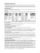
Warranty and Service Walter Meier (Manufacturing) Inc., warrants every product it sells. If one of our tools needs service or repair, one of our Authorized Service Centers located throughout the United States can give you quick service. In most cases, any of these Walter Meier Authorized Service Centers can authorize warranty repair, assist you in obtaining parts, or perform routine maintenance and major repair on your JET ® tools.
Table of Contents Warranty and Service..........................................................................................................................2 Table of Contents ...............................................................................................................................3 Warnings............................................................................................................................................4 Specifications ......................................
Warnings 1. Read and understand the entire owner's manual before attempting assembly or operation. 2. Read and understand the warnings posted on the machine and in this manual. Failure to comply with all of these warnings may cause serious injury. 3. Replace the warning labels if they become obscured or removed. 4. The hobby mill is designed and intended for use by properly trained and experienced personnel only.
21. Make your workshop child proof with padlocks, master switches or by removing starter keys. 22. Give your work undivided attention. Looking around, carrying on a conversation and “horse-play” are careless acts that can result in serious injury. 23. Maintain a balanced stance at all times so that you do not fall or lean against the hobby mill or other moving parts. Do not overreach or use excessive force to perform any machine operation. 24. Use the right tool at the correct speed and feed rate.
Specifications Model Number ........................................................................................................................ JHM-610 Stock Number .......................................................................................................................... 350200 Spindle stroke ...............................................................................................................1-3/16" (30mm) Maximum Distance, Spindle to Column ...................................
the plug provided-if it will not fit the outlet, have the proper outlet installed by a qualified electrician. Check with a qualified electrician or service personnel if the grounding instructions are not completely understood, or if in doubt as to whether the tool is properly grounded. Electrical Electrical Requirements When connecting the JHM-610 Hobby Mill to the power source outlet, the outlet must be properly grounded to protect the operator from electrical shock.
Unpacking Assembly Carefully unpack the machine and inspect for damage. Any damage should be reported immediately to your distributor and shipping agent. Do not discard the carton or packing material until the machine is set up and running satisfactorily. Referring to Figure 1: The Lifting Handwheel (14), Longitudinal Feed Handwheel (12), Cross Feed Handwheel (11), and Fine Feeding Handwheel (8) must be assembled prior to using the Hobby Mill.
Features Figure 1 – Features 1 Forward/Off/Reverse Switch 09. Lock Handle 2. Variable Speed Control Knob 10. Work Table 3. Fuse Box 11. Cross Feed Handwheel 4. Power Light (Green) 12. Longitudinal Feed Handwheel 5. Yellow Light 13. Quill Feed 6. High/Low Speed Selector Knob 14. Lifting Handwheel 7. Clutch Lever 15. DC Motor 8.
Important: Do not attempt to turn the switch directly from Forward to Reverse or from Reverse to Forward while the machine is running. To change the rotational direction, fist turn the switch to Off. After the machine stops completely, select Forward of Reverse Operating Instructions Routine Operating Instructions While performing the steps listed below, refer to the Features Drawing (previous page) for additional reference, if necessary.
Maintenance Always unplug the power cord before performing any inspection, maintenance, or cleaning. Before Each Use Inspect the general machine. condition of the Check for loose screws, misalignment or binding of moving parts. Check for cracked or broken parts. Check for damaged electrical wiring. Check for any other condition that may affect its safe operation. If abnormal noise or vibration occurs, have the problem corrected before further use. Do not use damaged equipment.
Assembly Drawing 12
Parts List Index No. Part No. Description Size Qty 1 .............. TS-1532042 ............Pan Head Machine Screw .................................M4x12........................ 2 2 .............. JHM610-02..............Motor Cover ....................................................................................... 1 3 .............. TS-1503031 ............Socket Head Cap Screw ...................................M6x12........................ 3 4 .............. TS-1551041 ............Lock Washer ......
Index No. Part No. Description Size Qty 56 ............ JHM610-56..............Worm Base ........................................................................................ 1 57 ............ JHM610-57..............Worm Gear ........................................................................................ 1 58 ............ JHM610-58..............Spacer ............................................................................................... 1 59 ............ JHM610-59..............Pin .
Index No. Part No. Description Size Qty 126 .......... JHM610-126............Control Label ...................................................................................... 1 127 .......... JHM610-127............Screw ..............................................................ST2.9x6.5 .................. 4 128 .......... JHM610-128............Power Cord with Plug.......................................................................... 1 129 .......... JHM610-129............Caution Label .......
Wiring Diagram 16