
Product Manual

13
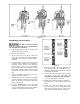
9. Lower load at destination. If both UP and
DOWN commands must be used during
lowering, pause for a moment between each
reversal of load direction.
10. Slowly allow weight to shift from hoist to
ground or new support. Do not approach load
until all tension is out of chain and load is
stable.
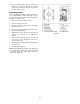
Adjustments
Safety Clutch Adjustment
The load limitation of the safety clutch has been set
to within 1.3 to 1.8 times the rated load of the hoist.
Generally, the safety clutch will not require
adjustment. But if the hoist ever fails to lift the rated
load while the rotor is turning, the safety clutch
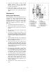
must be re-adjusted. Proceed as follows (see
Figure 14):
1. Suspend the rated load in the bottom hook.
2. Push the UP button to create tension on the
load chain, but do not raise the load off the
ground.
3. Disconnect the power source, and remove the
gear side cover.
4. Loosen the screw (G), open the plate (J), and
push down the adjusting shaft (K) until it fully
engages the adjusting circle nut (L). Rotate the
nut (H) clockwise to tighten the adjusting circle
nut (L).
5. Pull the adjusting shaft (K) out of engagement
with the adjusting circle nut (L). Then close the
plate (J) and tighten screw (G).
6. Connect hoist to power source, and push the
UP button on the pendant control. The hoist
should now lift the rated load. If it will not lift
the load, disconnect power and repeat steps 4
and 5 to tighten the adjusting circle nut until it
can lift the rated load.
7. Now change the load to within 1.3 to 1.8 times
the rated load, then push the UP button. The
hoist should NOT be able to lift the load. If it
can lift the load, repeat steps 4 and 5, rotate
the adjusting nut (H) and loosen adjusting
circle nut (L) until the hoist cannot lift the load.
8. Unload the hoist and repeat step 6 with the
original rated load. The hoist should now be
able to lift the original rated load. If it does not,
repeat steps 6 and 7 until the hoist operates
with the rated load only, but not with the 1.3 to
1.8 times rated load.
9. Unload the hoist, and re-install the gear side
cover.
Figure 14