This .pdf document is bookmarked Operating Instructions and Parts Manual Non-Ferrous Manual Cold Saw Models: J-CK350-2, J-CK350-4 JET 427 New Sanford Road LaVergne, Tennessee 37086 Ph.: 800-274-6848 www.jettools.com Part No.
1.0 Warranty and Service JET® warrants every product it sells against manufacturers’ defects. If one of our tools needs service or repair, please contact Technical Service by calling 1-800-274-6846, 8AM to 5PM CST, Monday through Friday. Warranty Period The general warranty lasts for the time period specified in the literature included with your product or on the official JET branded website. JET products carry a limited warranty which varies in duration based upon the product.
2.0 Table of Contents 1.0 Warranty and Service............................................................................................................................. 2 2.0 Table of Contents ................................................................................................................................... 3 3.0 IMPORTANT SAFETY INSTRUCTIONS ............................................................................................... 4 4.0 About this machine and manual.................
3.0 IMPORTANT SAFETY INSTRUCTIONS Read and understand the entire owner's manual before attempting assembly or operation. Read and understand the warnings posted on the machine and in this manual. Failure to comply with all of these warnings may cause serious injury. Replace the warning labels if they become obscured or removed. The cold saw is designed and intended for use by properly trained and experienced personnel only.
Do not stand on the machine. Serious injury could occur if the machine tips over. Never leave the machine running unattended. Turn the power off and do not leave the machine until it comes to a complete stop. Remove loose items and unnecessary work pieces from the area before starting the machine.
5.0 J-CK350 Features 6.0 Specifications Model ........................................................................... J-CK350-2 .............................................. J-CK350-4 Stock Number .................................................................... 414203 .................................................... 414207 Disc Blade Disc diameter ........................................................ 14" (350mm) ........................................... 14" (350mm) Hole diameter .........
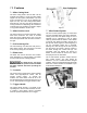
.0 Features 7.1 Miter Cutting Head The miter cutting head is the unit that cuts the material and consists of a cast iron base, blade support unit and guard, transmission unit, and motor. The depth of cut is set by adjusting the depth cut stop. The miter cutting head swivels and locks into -45º, 90º, and +45º by means of a locking mechanism. Depressing the mechanism overrides the lock, permitting the head to adjust to any position between -45º and +45. Figure 1 7.2 Miter Position Lock 7.
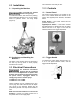
.0 Installation The cold saw is now ready for use. 8.1 Unpacking the Machine 10.0 Controls 10.1 Control Panel Do not handle the packed machine using slings. The Control Panel (Figure 4) is located on the front of the cabinet stand and consists of the Power and High/Stop/Low switches, described below. To install the machine, first remove the packing, paying particular attention not to cut any electric wires or hydraulic hoses. Lift using straps (Figure 3).
3. A detent mechanism locks the head in the -45º, 90º and +45º positions to prevent the head from rotating. For a miter position other than -45º, 90º and +45º, press the lever (C) to release while rotating the head. 11.0 Operation Before using the machine: Check that safety devices, such as blade guards, are in position and work perfectly and that personal safety requirements are complied with. 4. When the desired cutting angle is set, move miter position lock (A) to the left to secure.
12.5 Changing the Saw Blade 12.0 Maintenance The cold saw must not be connected to the power source when changing saw blades. Failure to comply may result in serious injury! 12.1 Maintenance Requirements All maintenance must be carried out with the power switched off. Failure to comply may result in serious injury! To change the saw blade: 1. Switch off the machine. 2. Release the lower disc guard.
12.7 Lubrication 12.9 Air Prep Unit For long life and trouble-free operation, it is essential that this machine be kept well lubricated. The vise and leadscrew should be oiled daily. Pivot joints and bearings should be greased weekly. Referring to Figure 14: Required Maintenance Recommended lubricants Check weekly. Drain water from the trap when the level exceeds the redline. Grease fittings Texaco Starplex 2 or equivalent Vice and Leadscrew Regal R & O 68 12.
resulting in poor cutting (same situation with soft materials), greater shearing stress and hence breakage of the blade. 13.0 Blades When using the J-CK350 cold saw, it is important to select the correct type of blade for the material to be cut. This section explains the limitations and specific applications of the different types of blades.
Teeth Shape ”C” TYPE SHARPENING (HZ) Coarse toothing with roughing tooth raked on both sides and non--raked finishing tooth – The roughing tooth is about 0.3 mm higher. Coarse toothing with roughing tooth and finishing tooth – Used in saws with pitch greater than or equal to 5 mm for cutting ferrous and non-ferrous materials with solid or solid-profiled Figure 19 sections.
.0 Troubleshooting J-CK350 Cold Saw 14.1 Blade and Cutting Problems Problem Teeth breaking Rapid tooth wear Broken blade Probable Cause Solution Incorrect lubricant/coolant fluid Ensure proper coolant flow. Material too hard Check the cutting speed, feed speed and air pressure parameters and the type of blade you are using. Disc not worn--in correctly With a new blade it is necessary to start cutting at half feeding speed.
14.2 Machine Fault & Operating Problems Problem Probable Cause Solution Electrical power supply Check: the phases; the cables; the plug; the socket. Also check that the motor connections are in place. Transformer Check that the voltages are present both on the input and output. Otherwise replace. Contactor Check that the phases in it are present both on the input and output, that it is not jammed, that it closes when powered and that it is not causing short circuits.
15.1.1 Stand Assembly – Parts List Index No. Part No. Description Size Qty 1 ............... FK350-601G ............ Cabinet Stand ...................................................... .................................... 1 2 ............... CK350-002 ............... Air Unit ................................................................. .................................... 1 3 ............... FK350-603 ............... Cam Switch .......................................................... ...........
15.1.
15.2.1 Head Assembly – Parts List Index No. Part No. Description Size Qty 1 ............... J-CK350-201G ......... Head Body ........................................................... .................................... 1 2 ............... CK350-202 ............... Spindle ................................................................. .................................... 1 3 ............... CK350-203 ............... Spindle Housing ................................................... ...............
15.2.
15.3.1 Base Assembly – Parts List Index No. Part No. Description Size Qty 1 ............... FK350-101G ............ Base ..................................................................... .................................... 1 2 ............... FK350-102G ............ Hinge Body........................................................... .................................... 1 3 ............... FK350-103G ............ Locking Mount ...................................................... ................
15.3.
15.4.1 Manual Vise Assembly – Parts List Index No. Part No. Description Size Qty ................. FK350-300 ............... Complete Vise Assembly (includes index #1-32) ...................................... 1 ............... J-FK350-301G ......... Base ..................................................................... .................................... 1 2 ............... J-FK350-302 ............ Front Vise Jaw (LH Thread) ................................. ....................................
15.4.
15.5.1 Guard Assembly – Parts List Index No. Part No. Description Size Qty 1 ............... J-CK350-401 ............ Guard A ................................................................ .................................... 1 2 ............... J-CK350-402 ............ Guard B ................................................................ .................................... 1 3 ............... J-CK350-403G ......... Chute.................................................................... ........
15.5.
15.6.1 CK350 Mist Coolant Assembly – Parts List Index No. Part No. Description Size Qty 1 ............... CK350-701 ............... Coolant Block ....................................................... .................................... 1 2 ............... CK350-702 ............... Coolant Nipple ..................................................... .................................... 1 3 ............... CK350-703 ............... Coolant Nozzle ..................................................... ..
15.6.
15.7.1 In-Feed Table – Parts List and Exploded View Index No. Part No. Description Size Qty 1 ............... FK350-701 ............... Bracket ................................................................ .................................... 1 2 ............... FK350-702 ............... Stand .................................................................... .................................... 1 3 ............... FK350-703 ............... Leveling Foot ............................................
15.8.1 Out-Feed Table Parts List and Exploded View Index No. Part No. Description Size Qty 1 ............... FK350-801 ............... Guide Block .......................................................... .................................... 1 2 ............... FK350-802 ............... Guide Rail ............................................................ .................................... 1 3 ............... TS-1502051 ............. Socket Head Cap Screw ......................................
15.9.1 Stock Stop Assembly – Parts List and Exploded View Index No. Part No. Description Size Qty 1 ............... FK350-501 ............... Block .................................................................... .................................... 1 2 ............... FK350-502 ............... Shaft ..................................................................... .................................... 1 3 ............... FK350-503 ............... Stop Rod ........................................
16.
427 New Sanford Road LaVergne, Tennessee 37086 Phone: 800-274-6848 www.jettools.